
Deep pocket CNC milling becomes difficult when cavity depth forces the use of long-reach tools, restricts chip evacuation and reduces cutting-system rigidity.
As a practical design starting point, a pocket depth within approximately three times its narrowest width is generally economical. Ratios between 3:1 and 4:1 are often manageable with appropriate tooling, while deeper and narrower cavities require more careful review. Actual risk is determined not only by pocket depth, but also by tool diameter, tool overhang, internal corner radius, material, tolerance and access.
Long tools are more likely to deflect and chatter. This may produce tapered walls, dimensional variation between the top and bottom of the cavity, poor surface finish and increased tool wear. Deep blind pockets also trap chips and heat, increasing machining time and scrap risk.
This guide explains how pocket geometry affects tool reach, chatter, tolerance, inspection and total deep pocket machining cost, as well as the design changes that can improve manufacturability.
Deep Pocket CNC Milling at a Glance
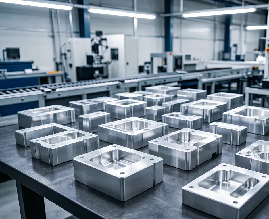
| Geometry or process condition | General risk level | Likely manufacturing approach |
| Pocket depth-to-width ratio up to about 3:1 | Standard | Conventional roughing and finishing |
| Ratio around 3:1–4:1 | Moderate | Longer tooling, controlled engagement and additional inspection |
| Ratio around 4:1–6:1 | High | Long-reach or necked tools, slower cutting and multiple finishing passes |
| Ratio above approximately 6:1 | Special review | Dedicated tooling, multi-axis access, redesign or alternative process |
| Deep pocket with large corner radii | Lower risk | Larger and more rigid cutters |
| Deep pocket with small corner radii | High risk | Small-diameter long tools and longer cycle time |
| Open or through pocket | Easier chip removal | Air or coolant can clear chips more effectively |
| Deep blind pocket | Higher risk | Controlled chip evacuation and repeated clearing cycles |
These ranges are general DFM references rather than fixed machining limits. A wide aluminum pocket with relaxed tolerances may be easier than a shallower stainless steel cavity with small radii and tight wall-position requirements.
Pocket Depth, Tool Reach and Tool L/D Are Not the Same
Three ratios are commonly used when evaluating CNC pocket milling, but they describe different problems.
Pocket depth-to-width ratio
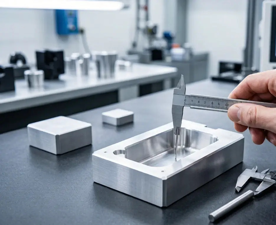
This compares pocket depth with the narrowest usable cavity width.
A wide cavity allows a larger cutter. A narrow cavity limits tool diameter and increases the likelihood that the cutter will be long and flexible.
The ratio is useful during CAD review, but it does not directly measure actual tool rigidity.
Tool length-to-diameter ratio
The end mill length-to-diameter ratio compares effective tool overhang with cutter diameter.
This is the most direct indication of tool stiffness. As the ratio increases, the tool becomes more vulnerable to:
- Deflection
- Chatter
- Wall taper
- Tool breakage
- Poor surface finish
- Dimensional drift
The relevant length is the portion extending from the holder and needed to reach the feature—not the tool’s total catalog length.
Internal radius relative to pocket depth
The corner radius determines the largest cutter that can reach the complete pocket.
A deep cavity may appear wide enough for a large tool, but a small internal radius can force the manufacturer to use a much smaller cutter for the full depth. This creates a high tool L/D ratio even when the overall pocket width is relatively generous.
For that reason, pocket depth and corner radius should be reviewed together.
Why Long-Reach Tools Deflect and Chatter?
A cutting tool behaves like a cantilever. Increasing overhang reduces its lateral stiffness.
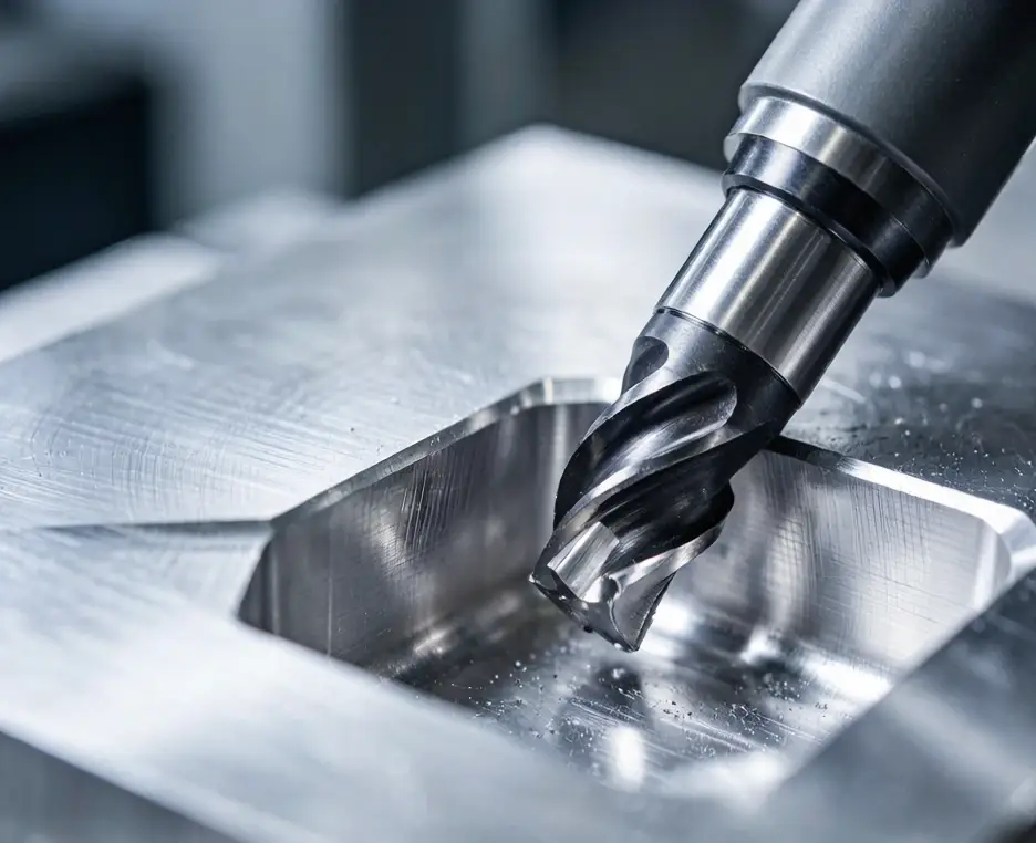
During long reach CNC milling, cutting forces push the tool away from the intended path. The tool then springs back, creating a repeating vibration that may become visible as chatter marks.
Typical results of tool deflection
Tool deflection may cause:
- The bottom of a pocket to be narrower than the top
- Tapered or bowed sidewalls
- Material left in internal corners
- Uneven wall thickness
- Poor positional accuracy
- Inconsistent floor dimensions
In some toolpath directions, the cutter may move away from the wall and leave excess material. Under different engagement conditions, it may spring into the surface and create local overcut.
Signs of CNC milling chatter
Common signs include:
- Wavy or repeated marks on the wall
- A high-pitched or irregular cutting sound
- Rapid tool wear
- Poor finish near corners
- Variation between successive passes
- Burrs or edge damage
Chatter is not only a cosmetic problem. It can affect deep pocket machining tolerance, shorten tool life and increase the risk of part rejection.
Why corners are especially difficult?
When a cutter enters an internal corner, its engagement angle increases. If the corner radius is close to the cutter radius, the tool may temporarily contact a much larger amount of material.
In a deep cavity, this sudden load is applied to a long and flexible tool. Increasing the part radius slightly above the cutter radius allows a smoother toolpath and reduces peak cutting force.
Chip Evacuation and Heat in Deep Pockets
Deep blind cavities restrict the movement of chips and coolant.
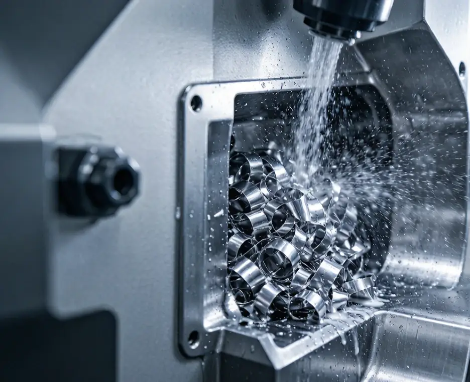
If chips remain in the pocket, they may be cut again. Chip recutting increases heat, scratches the surface and creates unpredictable tool loads.
Common chip-evacuation problems
Deep cavities can experience:
- Chips collecting in the bottom corners
- Coolant failing to reach the cutting edge
- Long chips wrapping around the tool
- Compressed chips damaging the floor
- Chips blocking narrow passages
- Heat buildup around the cutter
The problem becomes more severe in narrow blind pockets because chips have only one exit direction.
Material differences
Aluminum produces a large chip volume and can form built-up material on the cutting edge if chips are not removed efficiently.
Stainless steel creates tougher chips and greater cutting heat. Titanium retains heat near the tool edge, increasing the importance of controlled engagement and coolant delivery.
Engineering plastics may soften or smear when heat accumulates.
Chip-control methods
Depending on the material and geometry, the machining plan may use:
- Air blast
- Flood coolant
- Through-tool or through-spindle coolant
- High-pressure coolant
- Repeated tool retraction
- Adaptive toolpaths with open chip channels
- Machining from an open side
- Converting a blind pocket into a through-feature
An open or through pocket is normally easier to machine than a closed cavity of the same depth because chips and coolant have a clearer path.
How Deep Pockets Affect Tolerance and Surface Finish?
Deep features are not equally difficult at every level of the cavity.
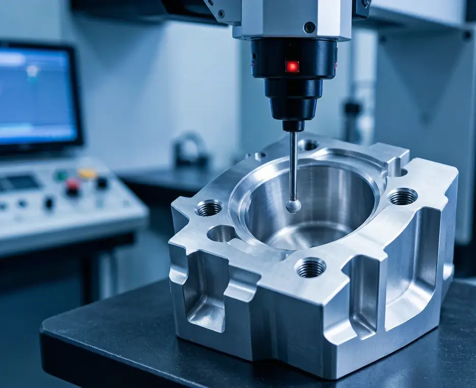
Dimensional variation from top to bottom
The top portion of a pocket is machined close to the tool holder, where the system is more rigid. At greater depth, the effective overhang increases and tool deflection becomes more significant.
A deep sidewall may therefore show:
- Different dimensions at the top, middle and bottom
- Wall taper
- Profile variation
- Uneven corner stock
- Different surface texture at different depths
Floor accuracy
The pocket floor may be affected by:
- Tool deflection during entry
- Chips trapped beneath the cutter
- Limited coolant access
- Long-tool vibration
- Thermal growth
- Incomplete material removal near corners
If floor flatness or depth is functionally critical, it should be identified separately from general pocket dimensions.
Avoid tightening every deep-pocket surface
Not every internal surface needs the same tolerance.
The drawing should distinguish between:
- Mating walls
- Locating surfaces
- Sealing surfaces
- Functional pocket floors
- Non-functional clearance walls
- Cosmetic internal surfaces
Relaxing non-functional wall and floor requirements can reduce finishing passes and inspection time without affecting assembly performance.
Inspection access
Deep pockets are also difficult to measure.
Depending on cavity geometry, inspection may require:
- Long CMM probes
- Stylus extensions
- Optical measurement
- Bore or depth gauges
- Custom gauges
- Measurement at several wall heights
Long probes can introduce their own access and stiffness limitations. The inspection method should therefore be planned before confirming a tight deep-pocket tolerance.
Tooling and Machining Strategies for Deep Pockets
Stable deep cavity milling normally uses different tools and cutting strategies at different stages.
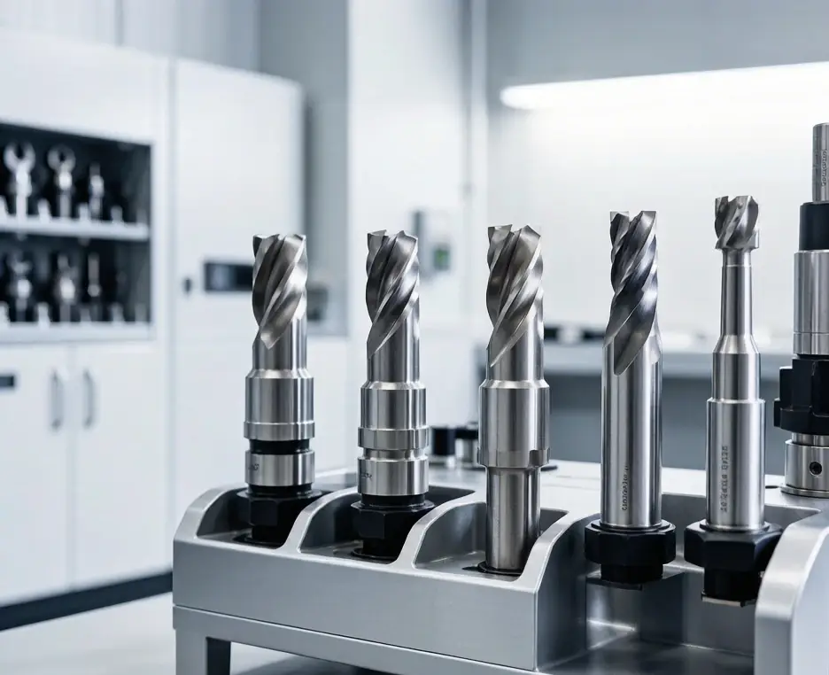
Use short tools first
Most of the upper cavity should be rough-machined with the shortest and largest tool that can reach it.
A longer tool should be introduced only when the remaining depth requires it. Using one extended-reach cutter for the complete pocket creates unnecessary deflection and cycle time.
Use necked or relieved-shank tools
A necked tool has a cutting diameter with a reduced non-cutting neck behind it.
This allows the tool to reach deeper without requiring the entire cutting edge to be excessively long. However, the neck diameter still affects stiffness and must clear the surrounding wall.
Separate roughing and finishing
A typical process may include:
- Short-tool roughing
- Extended-tool roughing
- Semi-finishing with controlled allowance
- Wall finishing
- Floor finishing
- A light spring pass where necessary
Semi-finishing creates a more consistent allowance before the final pass. This helps reduce sudden changes in cutting force.
Maintain consistent tool engagement
Adaptive or trochoidal toolpaths can maintain a more stable cutting load than full-width slotting.
Helical or ramp entry is usually preferable to forcing the tool vertically into solid material.
Use spring passes carefully
A spring pass repeats the finishing path with little or no additional programmed offset.
It can remove material left because of tool deflection, but repeated passes also add cycle time and do not correct an unstable setup. Spring passes should support a stable process rather than replace proper tool selection.
Consider plunge milling
Plunge milling directs more cutting force along the tool axis, where the system is usually stiffer.
It may help rough selected deep cavities, but it is not ideal for every pocket shape and does not eliminate the need for wall finishing.
Design Changes That Reduce Deep-Pocket Risk
The most effective cost reduction often comes from changing the geometry before machining begins.
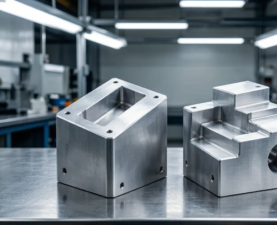
Increase pocket width
A wider pocket allows a larger cutter and improves chip evacuation.
Even a small width increase may significantly improve tool stiffness.
Increase internal radii
Larger radii allow larger-diameter tools and smoother corner movement.
Small internal radii should be limited to areas where they are functionally necessary.
Use stepped cavities
A stepped cavity keeps the upper section wide and only narrows near the bottom.
The manufacturer can remove most material with a large, short tool and use a long-reach cutter only for the deepest section.
Open one side
Adding a side opening can improve:
- Tool access
- Chip evacuation
- Coolant delivery
- Inspection access
- Effective tool length
Convert a blind pocket into a through-feature
A through-feature removes the closed floor and provides a clear chip-exit path.
It may also allow machining from both sides.
Machine from two directions
When the design permits, splitting the total depth between two machining directions can greatly reduce effective tool reach.
Datum relationships and alignment between both sides must still be controlled.
Split the component
A very deep enclosure may be more economical as two simpler parts.
The final design can use screws, locating pins, welding, brazing or adhesive bonding, depending on strength and sealing requirements.
Assembly cost must be compared with the machining risk of the original one-piece design.
When 5-Axis Machining Helps?
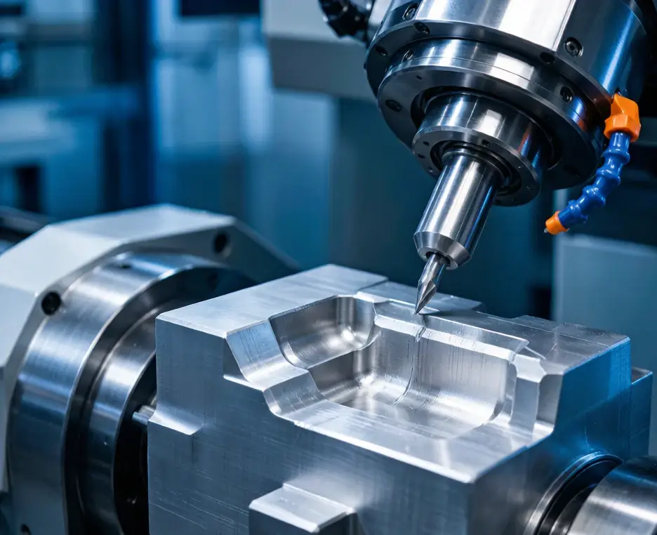
5 axis CNC machining can improve deep-pocket access by changing the angle between the cutter and the workpiece.
This may allow the manufacturer to:
- Shorten effective tool overhang
- Avoid collision with high walls
- Reach angled cavity surfaces
- Reduce part repositioning
- Improve relationships between multi-face features
Five-axis machining is valuable when geometry prevents direct vertical access or when several deep features must be controlled from related datums.
It is not automatically required for every deep pocket. A top-access cavity with adequate width and radii may remain more economical on a 3-axis machining center.
Machine selection should be based on effective tool reach, setup count, tolerance and total process cost.
What Determines Deep Pocket CNC Milling Cost?
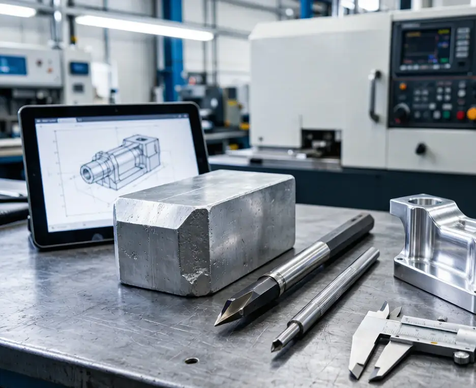
The deep pocket machining cost is affected by more than material-removal volume.
Tooling
Long-reach, necked or specialized cutters cost more and may have shorter usable life.
Several tool lengths may be required to complete one cavity.
Machine time
Cycle time increases because deep pockets often require:
- Smaller step-downs
- Lower feed rates
- Repeated chip-clearing moves
- Semi-finishing
- Multiple wall passes
- Spring passes
- More cautious entry and exit paths
Material
Aluminum allows faster material removal than stainless steel or titanium. Harder or heat-sensitive materials increase tool wear and cutting-control requirements.
Tolerance and finish
Tight wall position, floor flatness and low surface roughness require additional finishing and inspection.
A non-functional internal clearance pocket will generally cost less than a precision mating cavity of the same size.
Inspection
Deep features may require CMM programming, long probes or custom measurement methods.
Scrap risk
A broken tool or dimensionally incorrect wall discovered near the end of machining can result in the loss of both the raw material and all previous machine time.
Cost often rises more rapidly once geometry moves beyond the stable standard-tool range.
Three Deep Pocket CNC Milling Examples
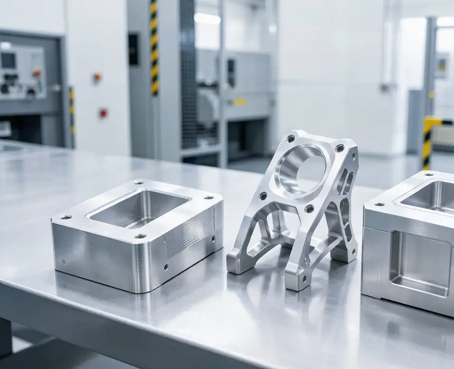
Semiconductor fixture base
A large aluminum fixture may contain a deep blind cavity with a controlled floor and locating features.
Main risks include chip accumulation, floor distortion and wall-position variation. A practical process may use staged roughing, stable plate stock, short tools for the upper cavity and final inspection after unclamping.
A wider opening or stepped cavity may reduce tool reach without changing the fixture’s main function.
UAV lightweight bracket
A UAV bracket may combine deep pockets with thin remaining walls.
The challenge is balancing weight reduction with rigidity. Removing more material may increase both part deformation and tool vibration.
Potential improvements include larger internal radii, temporary supports and leaving thicker local sections around mounting features.
Robotic housing
A robotic or electronic housing may include deep connector pockets and narrow cable channels.
Small internal radii may force the use of a long, small-diameter tool. Opening one side, using a removable cover or splitting the housing into two components may reduce machining time and improve inspectability.
Information Required for an Accurate Quote
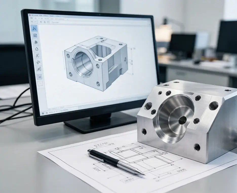
For a reliable deep pocket CNC milling quotation, provide:
- STEP or STP model
- 2D technical drawing
- Material and material condition
- Pocket depth and narrowest width
- Internal corner radii
- Open, blind or through geometry
- Critical wall and floor tolerances
- Surface-roughness requirements
- Quantity
- Finishing requirements
- Inspection and reporting requirements
Mark which internal surfaces are functional. This prevents the supplier from applying unnecessary precision to the complete cavity.
How SinoRise Supports Deep Pocket Milling Projects?

SinoRise reviews pocket geometry, tool access, material, wall thickness, tolerance, finishing and inspection before production.
Depending on the part, the manufacturing plan may use 3-axis milling, positional multi-axis machining, 5-axis machining, wire cutting or coordinated secondary processes.
SinoRise operates more than 40 precision machining machines and uses inspection equipment including 2.5D measuring systems, digital height gauges and CMM equipment. Its ISO 9001 quality system supports projects for medical equipment, UAVs, semiconductor systems, robotics, optical instruments and automotive or motorcycle components.
For prototypes and small batch CNC machining, early DFM review can identify features that need long-reach tooling, additional inspection or a lower-risk geometry before production begins.
Frequently Asked Questions
What is considered a deep pocket in CNC milling?
A pocket is often treated as deep when its depth exceeds approximately three to four times its narrowest width, or when the required tool overhang begins to dominate rigidity and chip evacuation.
What is a recommended pocket depth-to-width ratio?
A ratio up to approximately 3:1 is a practical low-risk starting point. Ratios between 3:1 and 4:1 are often manageable, while deeper features require more detailed review.
Why do long end mills chatter?
Long overhang reduces tool stiffness. Cutting forces cause the cutter to bend and vibrate, producing chatter marks, wall taper and dimensional variation.
Can a deep pocket hold ±0.01 mm?
It may be possible on selected features, but feasibility depends on depth, tool diameter, material, wall rigidity, temperature and inspection access. It should be confirmed through feature-specific review.
Does a larger corner radius reduce cost?
Usually yes. A larger radius allows a larger and more rigid cutter, reduces corner engagement and may shorten both roughing and finishing time.
How are chips removed from deep blind pockets?
Methods include air blast, coolant, through-tool coolant, repeated retraction and toolpaths that maintain open chip channels.
When should 5-axis machining be used?
Five-axis machining is useful when it shortens effective tool reach, avoids holder interference or reduces setup changes for multi-face deep features.
Why are deep pockets expensive?
They require longer tools, slower machining, more toolpaths, additional chip control, greater inspection effort and carry a higher risk of tool failure or scrap.
Request a Deep Pocket Milling Review
Send SinoRise your 3D model, drawing, material, cavity dimensions, critical tolerances and production quantity.
Our engineering team will review tool reach, pocket geometry, chatter risk, inspection access and possible DFM improvements before quotation.
Contact SinoRise for a deep pocket CNC milling and manufacturability review.