
A standard end mill cannot produce a mathematically sharp 90-degree internal corner between two vertical walls. Because the cutter is round, it leaves an internal radius. A smaller tool can reduce that radius, but it also lowers rigidity, increases cycle time and becomes difficult to use in deep pockets.
The right solution depends on what the corner must do. A square component may only need enough clearance to sit inside a pocket. A keyway or internal hex may suit broaching. A through-profile with a very small radius may suit wire EDM, while a blind mold cavity may require sinker EDM.
This guide compares radius changes, dog-bone and T-bone reliefs, rest machining, broaching and EDM based on function, tolerance and cost.
Sharp Internal Corner Options at a Glance
| Method | Best suited to | Main limitation | Relative cost |
| Larger internal radius | Most pockets and general parts | Mating part must accept the radius | Lowest |
| Dog-bone or T-bone relief | Square parts fitting into milled pockets | Removes extra corner material | Low to moderate |
| Smaller tool and rest machining | Accessible corners needing a smaller radius | Deflection and longer cycle time | Moderate |
| Broaching | Square, hex, spline or keyway forms | Requires suitable tooling and access | Quantity-dependent |
| Wire EDM | Very small radii in through-profiles | Conductive parts only; requires wire access | High |
| Sinker EDM | Very small radii in blind cavities | Electrode preparation and slower processing | High |
The lowest-cost choice is normally the largest internal radius that still meets the part’s functional requirement.
Why CNC Milling Leaves an Internal Radius?
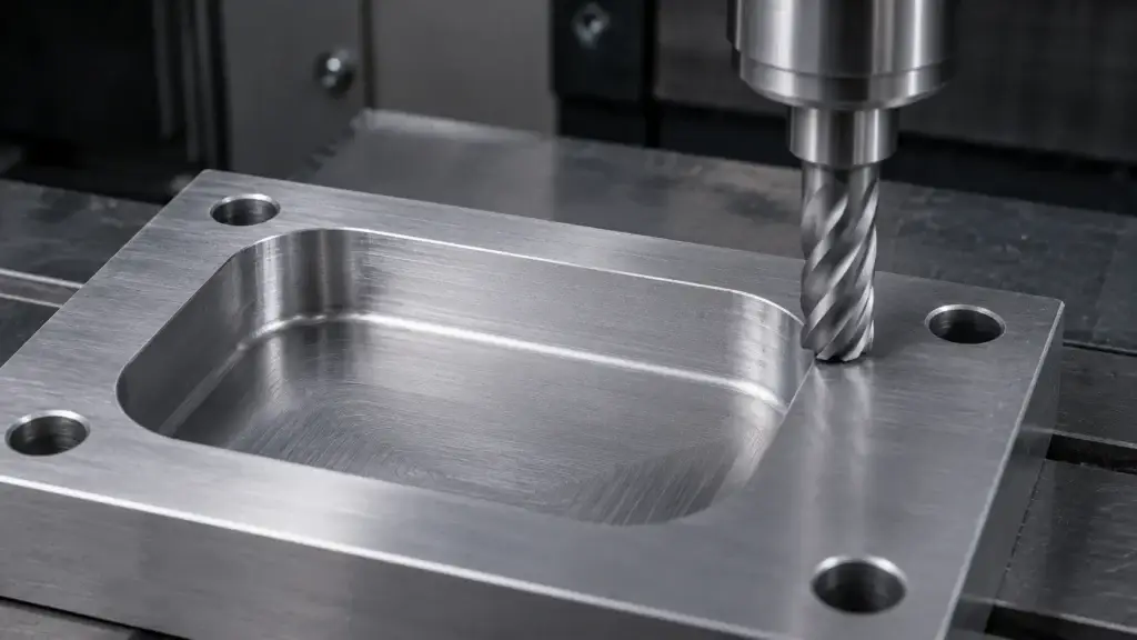
In the CNC milling process, the cutting edge rotates around the center of a circular tool. When the cutter follows two perpendicular walls, its profile cannot enter the theoretical intersection of those walls.
A 6 mm end mill has a nominal radius of 3 mm. In practice, the part radius should normally be slightly larger than the cutter radius. This gives the tool room to move through the corner without approaching full-width engagement, which can increase cutting force, chatter, wear and visible witness marks.
The problem becomes more difficult when the pocket is deep. A small-diameter tool must extend farther from the holder, reducing stiffness and increasing deflection. The minimum economical radius therefore depends on both cutter diameter and tool reach.
This limitation applies to wall-to-wall internal corners. External corners are easier because the tool can travel around the outside of the profile. Wall-to-floor transitions depend on the tool’s end geometry and any specified floor fillet.
First Identify the Real Requirement
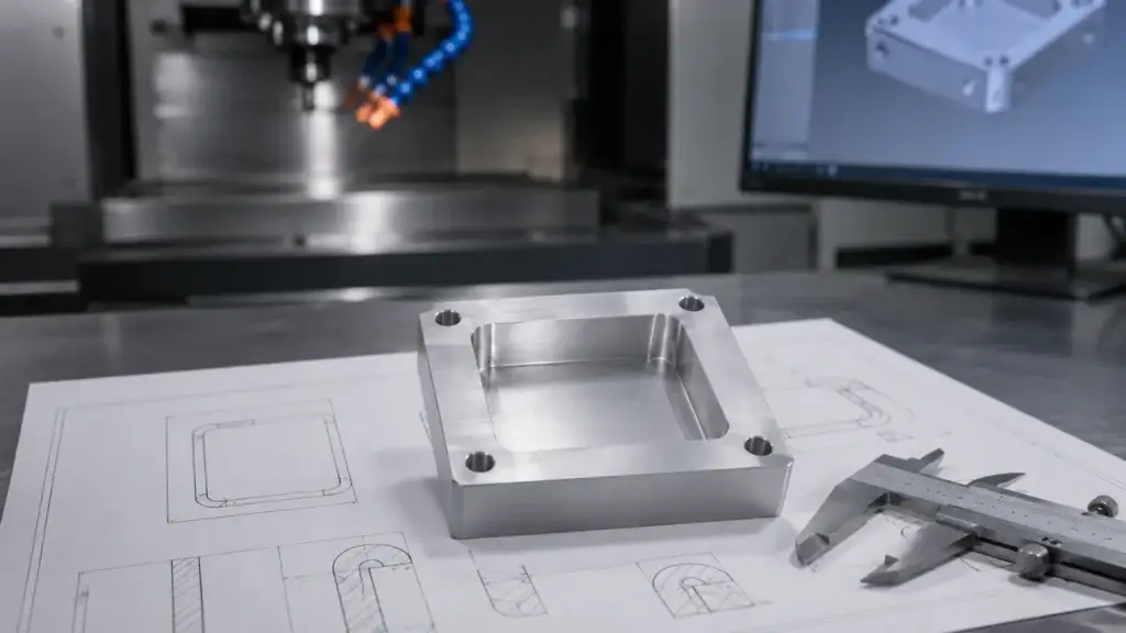
Before selecting a special process, determine why the drawing calls for a sharp corner.
Square-Part Clearance
A rectangular insert, connector or module may need to sit fully inside a pocket. The pocket does not need a true zero-radius corner; it only needs local clearance around the mating part’s outer corners.
A dog-bone, T-bone or chamfer on the mating component may solve the problem without EDM.
True Geometric Detail
A mold insert, die feature or precision interface may need a very small internal radius because the corner transfers shape to another part. This is more likely to justify EDM or another secondary process.
Regular Internal Profile
A square hole, internal hex, spline or keyway is a controlled repeating form that may be suitable for broaching.
Cosmetic Appearance
When the corner only needs to look sharp from a visible direction, a small-tool finishing pass, local manual finishing or a design change may be sufficient.
A useful drawing should specify the maximum acceptable radius and its function rather than only stating “R0” or “sharp corner.”
Option 1: Increase the Internal Corner Radius
Increasing the radius is the most stable and economical solution.
A larger radius allows the precision CNC milling supplier to use a larger, shorter cutter. This improves rigidity, chip evacuation, material-removal rate, tool life and dimensional repeatability.
It can also reduce tool changes. When one pocket includes several small radii, the supplier may need a large tool for roughing and one or more smaller cutters for cleanup. Standardizing non-critical radii simplifies programming and machining.
Another option is to add a chamfer or radius to the mating part’s external corners. Modifying a few accessible external edges is often easier than forcing a deep pocket to have very small internal radii.
The practical DFM question is not:
What is the smallest radius your CNC milling capabilities can produce?
It is:
What is the largest radius this assembly can accept?
Option 2: Use Dog-Bone or T-Bone Relief
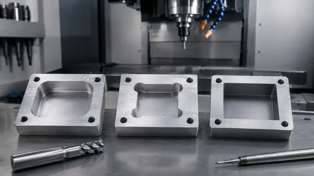
Dog-bone and T-bone reliefs remove extra material outside the theoretical square corner so a square mating part can clear the radius left by an end mill.
Dog-Bone Relief
A dog-bone relief places a circular cut at or around the corner. Depending on the drawing convention, it may extend diagonally or into both adjacent wall directions.
Dog-bone reliefs are often used in electronics housings, frames, router-cut plates and modular assemblies where fit is more important than maintaining an uninterrupted corner wall.
T-Bone Relief
A T-bone generally moves the clearance mainly along one wall. It may preserve more of the other wall or place the visible relief in a less critical direction.
Naming conventions vary between designers and suppliers, so the final geometry should be fully dimensioned rather than identified only by name.
Corner relief solves an assembly-clearance problem; it does not create a geometrically sharp corner. It can also affect:
- Wall thickness
- Seal paths
- Local stiffness
- Appearance
- Dirt or fluid retention
- Available contact area
The drawing should define the relief diameter, center location, direction and depth.
Option 3: Use a Smaller Tool and Rest Machining
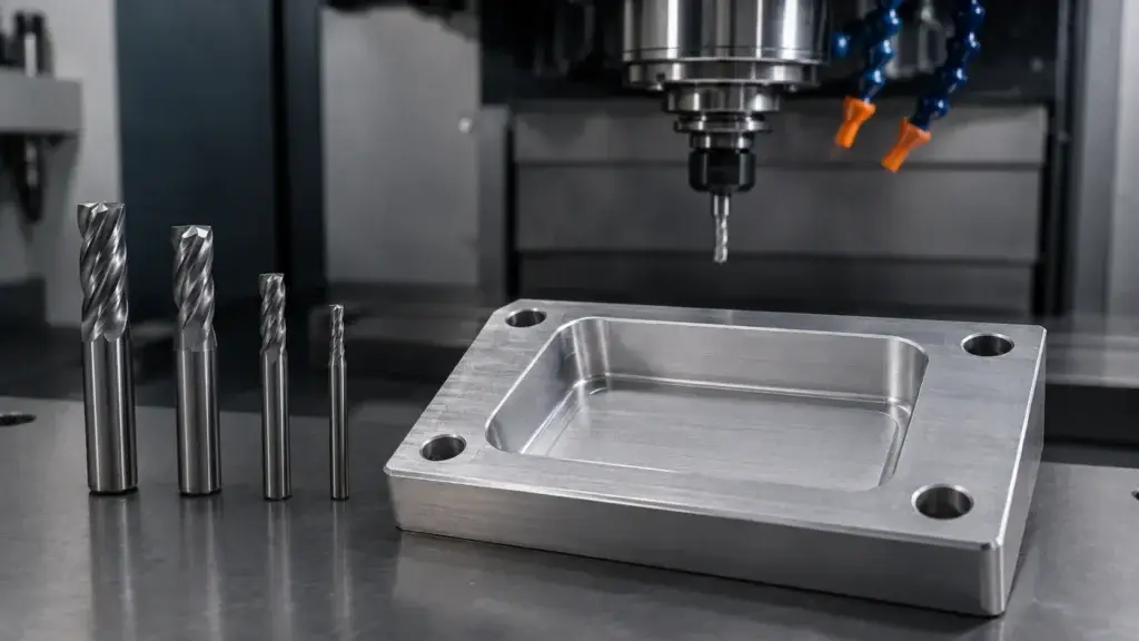
When a smaller but non-zero radius is required, the supplier can rough the pocket with a larger cutter and remove the remaining corner material with a smaller tool.
This is called rest machining because the second tool cuts only the stock left by the first. It is more efficient than using a small cutter for the entire pocket.
However, the cleanup tool still has lower rigidity and may require reduced feed, lighter cuts and additional inspection. Deep corners increase the tool length-to-diameter ratio, creating greater risks of:
- Chatter
- Tool deflection
- Tool breakage
- Wall taper
- Poor chip evacuation
- Inconsistent surface finish
Rest machining is most practical for accessible corners and moderate pocket depths. In deep stainless steel, titanium or hardened material, EDM may be more stable than prolonged small-tool milling.
The final radius is still determined by the smaller cutter. Rest machining cannot produce a true zero-radius corner.
Option 4: Use Broaching
Broaching uses a shaped tool to form a regular internal profile. The tool may move linearly through the part or be fed axially with a controlled wobbling motion, as in rotary broaching.
Typical broached features include:
- Square holes
- Internal hexagons
- Keyways
- Splines
- Serrations
Broaching can be efficient for repeated production and can create sharper profile transitions than conventional end milling. It may require:
- A suitable pilot hole
- A lead chamfer
- Adequate machine thrust
- Sufficient chip space
- Bottom relief in a blind feature
- A dedicated broaching tool
Broaching is not a universal solution for arbitrary pocket corners. A repeated internal hex or square drive may be a good broaching application. A large blind pocket with only one critical sharp corner usually is not.
Tooling cost also matters. A custom broach may be economical across repeat production but difficult to justify for only a few prototype parts.
Option 5: Use Wire EDM or Sinker EDM
Electrical discharge machining removes conductive material through controlled electrical sparks rather than direct cutting contact.
Wire EDM
Wire EDM feeds a thin wire through or around the workpiece to cut a two-dimensional profile.
It is suitable for:
- Through-slots
- Internal cutouts
- Die profiles
- Hardened tool inserts
- Small-radius through-corners
- Conductive materials
The wire requires an open edge or a start hole. The minimum internal radius depends on wire diameter, spark gap, machine control and finishing passes.
Wire EDM can create a much smaller radius than milling, but it cannot create a mathematical zero-radius corner.
Sinker EDM
Sinker EDM uses a shaped electrode to form a blind cavity. It is suited to:
- Mold details
- Deep ribs
- Narrow recesses
- Blind cavities
- Complex three-dimensional features
The process requires electrode design and manufacture. Electrode wear, flushing and finishing burns influence processing time and dimensional accuracy.
Both EDM processes are slower than standard milling and only work with electrically conductive materials. They may also leave a recast layer or altered surface zone. Critical fatigue, sealing or high-reliability applications may require additional finishing or defined surface-integrity requirements.
EDM should therefore be selected because the feature needs it, not simply because the drawing contains the word “sharp.”
How Method Selection Affects Tolerance and Cost?
| Cost factor | Radius or relief | Small-tool machining | Broaching | EDM |
| Standard tooling | Usually | Sometimes | Rarely | No |
| Secondary setup | Rare | Possible | Usually | Yes |
| Custom tooling | No | Rare | Often | Sinker EDM needs an electrode |
| Deep-feature risk | Lower | Higher | Process-dependent | Low cutting force, slower process |
| Best production stage | Prototype to volume | Prototype and low volume | Repeat production | Specialized features |
The biggest cost increase often occurs when a standard CNC milling operation becomes a multi-process manufacturing route.
Wire EDM may add separate programming, start-hole preparation, fixturing, scheduling and inspection. Sinker EDM adds electrode manufacturing. Broaching may be economical in volume but expensive for a small quantity when a custom tool is required.
Only the corners that affect fit or function should receive special processing.
How to Specify Internal Corners on a Drawing?
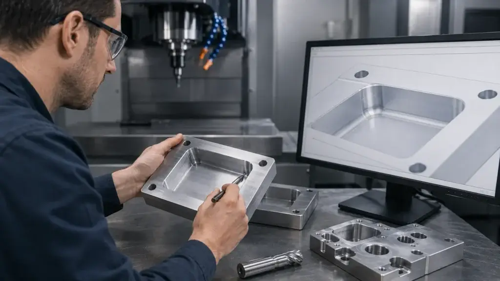
A clear internal-corner specification should include:
- Maximum allowable internal radius
- Exact controlled corner locations
- Wall-to-wall or wall-to-floor condition
- Pocket depth
- Whether dog-bone or T-bone relief is allowed
- Relief size, direction and center location
- Whether the feature is blind or through
- Mating-part geometry
- Dimensional and positional tolerances
- Surface-finish requirement
- Inspection method
- Condition before or after coating
Avoid notes such as:
- R0
- No radius
- Make sharp
- Sharp corner required
unless they are accompanied by a measurable acceptance limit.
When the corner is required for assembly, include the mating component or an assembly drawing. This allows the precision machining service to evaluate a lower-cost relief or mating-part modification.
Three Design Examples
Electronic or Robotic Housing
A square connector must sit inside a milled aluminum pocket. A normal internal radius prevents full insertion.
The first options are usually a chamfer on the connector or a dog-bone or T-bone relief. EDM is normally unnecessary unless relief is prohibited by sealing, appearance or structural requirements.
Semiconductor Positioning Block
A rectangular insert fits into a precision pocket. The locating walls and bottom surface may be critical, while the actual corner does not control position.
Relief can be placed outside the contact bands while preserving the functional datums. Inspection should focus on locating surfaces, relief position and final fit.
Hardened Mold Insert
A blind cavity contains narrow ribs and very small corner radii after heat treatment.
A practical route may combine CNC milling for roughing, small-tool rest machining for accessible details and sinker EDM for the deepest corners. Through-features in the same insert may instead suit wire EDM.
How SinoRise Reviews Sharp-Corner Features?
SinoRise reviews internal corners together with mating geometry, pocket depth, material, tolerance and production quantity.
The engineering team can evaluate whether a feature is better produced by a standard radius, dog-bone or T-bone relief, small-tool rest machining, broaching, wire cutting or another coordinated process.
The objective is to separate a true sharp-corner requirement from a fit problem that can be solved through a simpler and more stable design change.
For quotation, provide:
- STEP model
- 2D drawing
- Material
- Quantity
- Pocket depth
- Maximum allowed radius
- Mating-part information
- Inspection requirements
Frequently Asked Questions
Can CNC milling make a perfectly sharp internal corner?
No. A rotating round cutter leaves a radius between two vertical walls.
What is the minimum CNC internal corner radius?
It depends on cutter diameter, tool reach, pocket depth, material, tolerance and finish. The specified part radius should normally be slightly larger than the cutter radius.
What is a dog bone fillet CNC feature?
It is a corner-relief cut that lets a square mating part clear the internal radius left by milling.
What is the difference between dog-bone and T-bone relief?
A dog-bone generally distributes clearance around or diagonally beyond the corner, while a T-bone mainly extends along one wall. The final geometry should always be dimensioned.
Can 5-axis CNC eliminate internal corner radii?
No. Five-axis access can shorten tool reach or change the approach direction, but a round rotating cutter still leaves a wall-to-wall radius.
When should broaching be used?
Broaching is best for regular profiles such as squares, hexagons, keyways and splines when suitable access, pilot geometry and chip space are available.
Should I use wire EDM or sinker EDM?
Use wire EDM for accessible through-profiles. Use sinker EDM for blind cavities and three-dimensional recesses.
Can EDM create a zero-radius corner?
No. EDM can produce much smaller radii than milling, but wire diameter, spark gap or electrode geometry still defines the final corner.
Request an Internal Corner DFM Review
Send SinoRise your 3D model, drawing, material, pocket depth, maximum allowable radius, quantity and mating-part information.
The engineering team will review the function of each corner and recommend a practical route using radius optimization, internal corner relief, precision CNC milling, broaching or EDM.