
Precision CNC milling is not defined by a single tolerance value or a high-end machine. It is a controlled manufacturing process that connects drawing requirements, machine condition, fixture design, cutting strategy, inspection and documented feedback.
A supplier may state that it can achieve ±0.01 mm, but that figure alone does not show whether the tolerance can be maintained on a specific material, feature and production quantity. A more useful question is whether the supplier can produce the required dimension repeatedly, verify it with suitable inspection equipment and control dimensional drift throughout the batch.
This guide explains how CNC milling tolerances are specified, what affects machining accuracy, how inspection should be planned and how process control maintains consistent results from the first article to repeat production.
Quick Answer
Precision CNC milling combines stable machining, controlled setups, appropriate cutting tools, in-process measurement and final inspection. Tight tolerances should be applied only to functional features and verified with measuring equipment suited to the feature, tolerance and inspection risk.
Key Takeaways
- Tolerance, accuracy, repeatability and process capability describe different aspects of quality.
- A machine’s positioning accuracy does not equal the finished part tolerance.
- Fixtures, datums, tool wear, temperature and material behavior can affect dimensional results.
- First article inspection confirms the setup, while in-process inspection controls the remaining batch.
- CMM inspection is most valuable for complex geometry and GD&T, not every general dimension.
- Precision production requires a reaction plan for dimensional drift, not only a final inspection report.
Precision CNC Milling Tolerances at a Glance
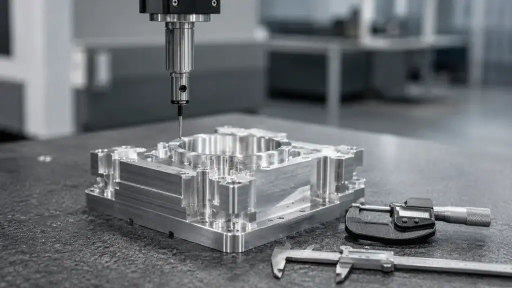
There is no universal tolerance that applies to every CNC-milled part. Achievable results depend on the material, feature size, part geometry, machine, setup, production environment and measurement method.
The following ranges are general planning references rather than guaranteed capabilities.
| Requirement level | Illustrative tolerance range | Typical application | Control required |
| General machined features | ±0.05 to ±0.10 mm | Outer dimensions, clearance features and non-critical pockets | Standard setup and conventional inspection |
| Precision features | ±0.01 to ±0.03 mm | Locating faces, mounting holes and controlled fits | Stable fixture, finishing passes and precision measurement |
| Tight-tolerance features | Below ±0.01 mm | Selected alignment, sealing or high-accuracy interfaces | Feature-specific review, environmental and process control |
| Complex GD&T requirements | Drawing-specific | Position, flatness, perpendicularity and profile | Datum planning, controlled setups and CMM inspection |
A tolerance should never be separated from its conditions. For example, ±0.01 mm on a short, rigid aluminum boss is not equivalent to the same tolerance on a tall thin wall, a deep stainless steel pocket or a feature machined after several repositioning operations.
The drawing must therefore identify which features are functionally critical and which can follow general machining tolerances.
Tolerance, Accuracy and Repeatability Are Not the Same
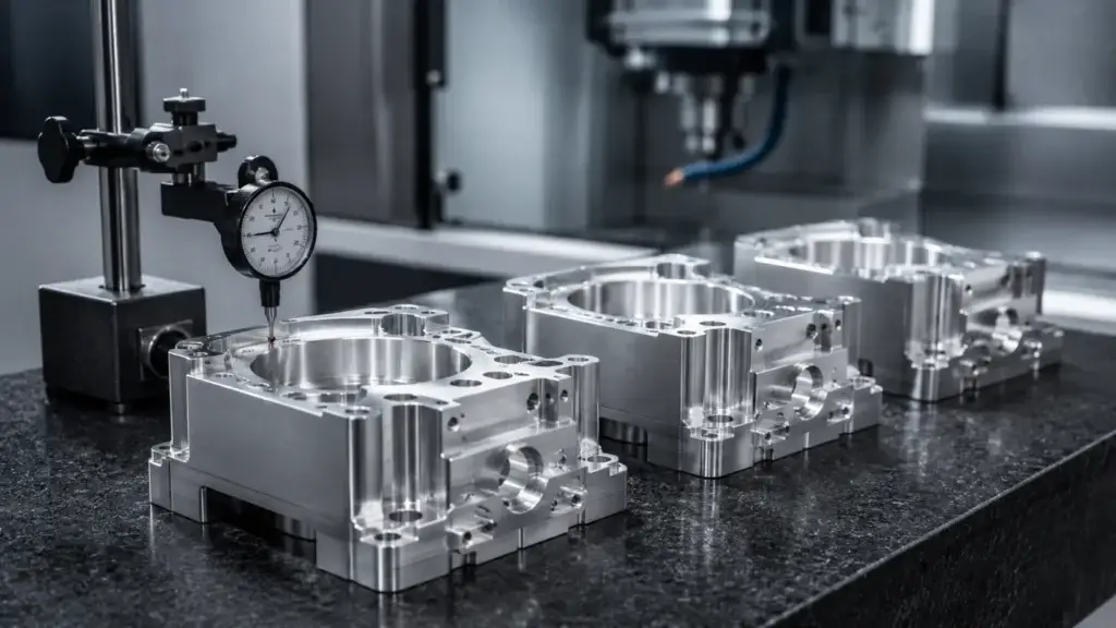
A reliable precision CNC machining project begins with clear terminology.
Tolerance
Tolerance is the permitted variation shown on the engineering drawing.
A dimension of 20.00 ±0.02 mm allows an acceptable result between 19.98 and 20.02 mm. The tolerance defines the acceptance range; it does not explain how the process will achieve it.
Accuracy
Accuracy describes how close the measured result is to the intended value.
A process producing parts close to 20.00 mm is accurate. A process producing every part around 20.018 mm may still be within tolerance, but it is operating close to the upper limit.
Repeatability
Repeatability describes how consistently the process produces the same result.
A process can be repeatable but inaccurate. For example, every part may measure close to 20.04 mm. The results are consistent, but outside the permitted tolerance.
Process capability
Process capability describes whether a stable process can continue producing parts within specification over time.
This is particularly important in batch production. One acceptable first article does not prove that the next 50 or 500 parts will remain within tolerance.
A capable process should be:
- Centered around the intended value
- Stable as tools wear
- Resistant to minor environmental variation
- Supported by defined inspection intervals
- Corrected before measurements cross the tolerance limit
This distinction is why high precision CNC milling should be evaluated as a production system rather than a one-time measurement.
What Controls Precision in CNC Milling?
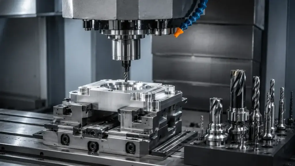
Finished-part accuracy is influenced by the entire machining route.
Machine condition and calibration
Machine rigidity, axis condition, spindle runout, backlash compensation and positioning performance all affect the result.
Regular maintenance and calibration reduce uncertainty, but machine specifications alone do not guarantee part accuracy. Cutting forces, fixtures and tool geometry still influence the finished component.
Fixture rigidity and datum strategy
The fixture must hold the part securely without deforming it.
An unstable setup can cause:
- Part movement during cutting
- Incorrect feature position
- Poor flatness
- Variation between batches
- Deformation after unclamping
The datum structure is equally important. Critical features should reference clear and functional datums rather than unrelated external surfaces.
Where possible, related precision features should be machined in the same setup. This reduces error introduced when the component is removed and repositioned.
Cutting tools and tool wear
A new tool and a worn tool do not produce identical results.
Tool wear can gradually change:
- Hole diameter
- Pocket width
- Wall location
- Surface roughness
- Burr formation
- Cutting temperature
For this reason, a controlled CNC milling process includes tool-life limits, visual checks and dimensional feedback. Critical tools may be replaced according to an established part count or measured wear condition rather than waiting for tool failure.
Tool overhang and deflection
Long, small-diameter tools are more likely to bend under cutting force.
Tool deflection becomes important when machining:
- Deep pockets
- Small internal radii
- Tall walls
- Narrow slots
- Hard materials
- Features requiring a fine surface finish
A feature may satisfy its nominal dimension in the CAD model but still be difficult to hold accurately if the cutter is not sufficiently rigid.
Roughing and finishing strategy
Precision surfaces should not normally be produced in a single heavy operation.
A controlled approach may include:
- Rough machining to remove most material
- A rest period or intermediate release from the fixture
- Semi-finishing to stabilize geometry
- Final finishing with a controlled tool and allowance
- Measurement and offset correction where required
This is especially valuable for parts with thin walls, extensive material removal or internal material stress.
Material behavior
Different CNC machining materials respond differently to cutting forces and heat.
Aluminum is highly machinable but may distort when significant internal material is removed. Stainless steel generates higher cutting forces and work-hardening risk. Titanium retains heat near the cutting edge. Engineering plastics can respond to clamping pressure, temperature and moisture.
The machining sequence must reflect the material rather than applying the same parameters to every component.
Thermal stability
Machines, tools, fixtures and workpieces expand as temperature changes.
For general machining, small thermal effects may not be significant. For tight-tolerance features, temperature differences between machining and inspection can influence the measured result.
Useful controls may include:
- Machine warm-up routines
- Stable workshop conditions
- Controlled coolant temperature
- Allowing parts to reach inspection-room temperature
- Measuring critical features at consistent stages
Number of setups
Each setup adds a new positioning operation.
A component requiring repeated flipping may accumulate error between features on different faces. 5 axis CNC machining or 3+2 positional machining can improve accuracy on suitable parts by reducing the number of times the component must be repositioned.
The benefit comes from fewer datum transfers—not simply from using a more advanced machine.
How to Specify CNC Milling Tolerances on a Drawing?
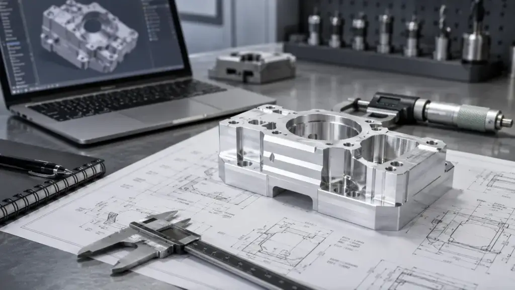
Clear drawings reduce quotation uncertainty and prevent unnecessary machining cost.
Set a general tolerance
The title block should define the general tolerance for dimensions without individual limits.
This prevents every non-critical dimension from being interpreted as a precision feature.
Identify critical dimensions separately
Tight tolerances should be limited to features that affect:
- Assembly
- Alignment
- Sealing
- Motion
- Optical positioning
- Bearing or shaft fits
- Safety
- Functional interchangeability
A supplier can then build the machining and inspection plan around those features.
Use GD&T with clear datums
Geometric dimensioning and tolerancing is useful when function depends on relationships rather than only feature size.
Common controls include:
- Position
- Flatness
- Parallelism
- Perpendicularity
- Profile
- Runout
A position tolerance without a clear datum reference is difficult to manufacture and inspect consistently. Datum selection should reflect how the part is located in the final assembly.
Separate size tolerance from position tolerance
A hole can have the correct diameter but still be incorrectly positioned.
The drawing should distinguish:
- Hole diameter
- Hole position
- Perpendicularity
- Depth
- Surface finish
- Relationship to other holes
This allows the supplier to choose the correct manufacturing and inspection method.
Specify surface roughness only where required
Surface roughness and dimensional tolerance are related but different requirements.
A tight dimensional tolerance does not automatically require a low Ra value, and a smooth surface does not guarantee dimensional accuracy.
Low roughness should be applied to functional surfaces such as:
- Sealing faces
- Sliding interfaces
- Bearing locations
- Optical mounting surfaces
- Precision contact surfaces
Clarify pre-treatment and post-treatment dimensions
Anodizing, electroplating, heat treatment and other finishing processes can affect dimensions or distortion.
The drawing or purchase specification should confirm:
- Whether dimensions apply before or after treatment
- Which surfaces require masking
- Whether coating thickness is included
- Which features must be reinspected
- Whether threads and precision holes need protection
This is especially important when machining and surface finishing services are managed by different suppliers.
Inspection Stages for Precision CNC-Milled Parts
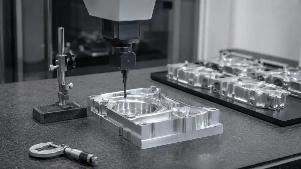
Inspection should begin before production and continue through the manufacturing process.
1. Drawing and inspection review
Before machining, engineering and quality teams should confirm:
- Critical characteristics
- Datum structure
- Measurement method
- Inspection frequency
- Required reports
- Acceptance criteria
A tolerance is only useful when the supplier has an appropriate method to verify it.
2. Incoming material inspection
Material control may include:
- Material grade verification
- Certificate review
- Raw-stock dimensions
- Surface condition
- Lot identification
For projects requiring traceability, the material lot should remain linked to the production and inspection records.
3. Setup verification
Before the first complete part is approved, the operator confirms:
- Fixture location
- Datum alignment
- Tool offsets
- Program version
- Workpiece orientation
- Critical tool clearance
Errors found at this stage are less costly than errors discovered after the full batch is complete.
4. First Article Inspection
First article inspection verifies that the planned process can produce a part matching the drawing.
An FAI may include:
- Critical dimensions
- GD&T characteristics
- Hole and thread verification
- Surface roughness
- Visual requirements
- Material and finishing records
Passing the first article confirms the initial setup, but it does not replace ongoing process checks.
5. In-process inspection
In-process measurement detects changes before they become batch-wide defects.
The inspection plan may monitor:
- High-risk dimensions
- Tool-wear-sensitive features
- Features produced early in the process
- Dimensions affected by heat or distortion
- Positions dependent on fixture stability
The results can be used to correct tool offsets or replace worn tools.
6. Final inspection
Final inspection verifies that completed parts meet the agreed specification.
Depending on the project, this may include:
- Dimensional inspection
- GD&T verification
- Surface roughness
- Thread checks
- Visual inspection
- Finishing verification
- Documentation review
7. Post-treatment reinspection
Critical features may need to be checked again after anodizing, plating, passivation or heat treatment.
This confirms that the complete manufacturing chain—not only the machined blank—meets the drawing.
8. Documentation and traceability
Required documents may include:
- FAI report
- CMM dimensional report
- Material certificate
- Surface-treatment certificate
- Final inspection report
- Lot number
- Nonconformance and corrective-action records
The documentation level should match the industry, feature risk and customer requirements.
Which Inspection Tool Should Be Used?
The best measuring device is determined by the feature, tolerance, geometry and inspection frequency.
| Inspection equipment | Suitable applications | Main limitation |
| Caliper | General lengths, widths and non-critical dimensions | Not suitable for very tight tolerances |
| Micrometer | Thickness, diameters and precise linear dimensions | Measures limited feature types |
| Height gauge | Heights, steps and datum-related measurements | Requires a stable reference surface |
| Bore gauge | Internal diameters and bore variation | Requires correct setup and master calibration |
| 2.5D optical system | Profiles, hole positions and small non-contact features | Limited for complex three-dimensional geometry |
| CMM | Position, profile, flatness and complex GD&T | Requires programming, setup and controlled measurement |
| Roughness tester | Ra and other surface-texture values | Does not verify dimensional geometry |
| Go/No-Go gauge | Fast functional checking in batch production | Provides acceptance status rather than full measurement data |
When is CMM inspection necessary?
CMM inspection is particularly useful when the drawing contains:
- Complex datum relationships
- Position tolerances
- Three-dimensional profiles
- Multiple related features
- Critical dimensions on different faces
- Detailed reporting requirements
Not every dimension needs to be measured by CMM. A micrometer may be faster and more appropriate for a simple precision thickness, while a functional gauge may be more efficient for a repeated assembly feature.
The inspection plan should use the simplest method that can reliably verify the requirement.
How Process Control Maintains Batch Consistency?
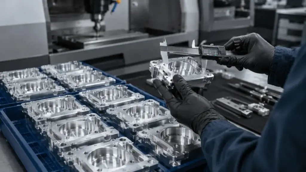
Quality cannot depend on sorting acceptable and unacceptable parts at the end of production.
Effective CNC process control uses inspection data to keep the process stable.
Monitor tool wear
Dimensions affected by a specific tool should be identified during process planning.
When measurements show a gradual trend, the operator can:
- Correct the tool offset
- Reduce the remaining tool-life limit
- Replace the cutter
- Check spindle or holder condition
- Inspect the next part more frequently
The objective is to act before the process crosses the tolerance boundary.
Define inspection frequency by risk
Inspection frequency should reflect:
- Tolerance severity
- Tool-wear rate
- Feature function
- Material behavior
- Batch size
- Fixture stability
- Previous production history
A safety-critical dimension may require 100% inspection. A stable non-critical feature may be checked by sampling.
Keep the process near nominal
A part measuring close to the tolerance limit may technically pass, but it provides little margin for subsequent variation.
For example, if a dimension is allowed from 19.98 to 20.02 mm, repeated results near 20.019 mm indicate that corrective action may soon be necessary.
A stable process should aim near the nominal value rather than intentionally running close to one limit.
Revalidate after significant changes
Additional verification may be needed after:
- Machine change
- Fixture change
- Program revision
- Material-lot change
- Tooling change
- Long production interruption
- Surface-treatment change
- Previous nonconformance
The required response depends on the importance of the affected features.
Three Precision CNC Milling Examples
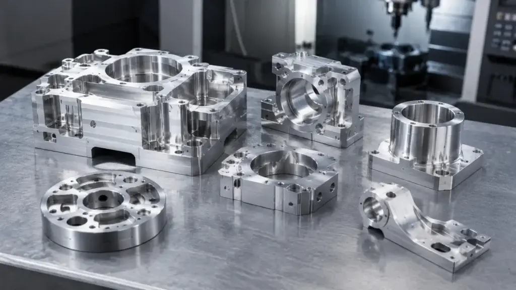
Optical mounting component
Critical requirements:
- Hole position
- Flat mounting face
- Perpendicular optical interface
- Surface treatment
Manufacturing risks:
- Datum transfer between faces
- Coating buildup around mounting holes
- Distortion of the mounting surface
Control approach:
- Machine related features from a common datum
- Verify position and perpendicularity by CMM
- Protect critical surfaces during finishing
- Reinspect mounting features after treatment
Robotic multi-face housing
Critical requirements:
- Bearing-hole relationship
- Motor mounting position
- Multi-face alignment
- Repeatable assembly
Manufacturing risks:
- Accumulated error from several setups
- Tool access to side features
- Distortion after internal material removal
Control approach:
- Use 5-axis or positional multi-axis machining where appropriate
- Rough and finish in controlled stages
- Complete related features with fewer datum transfers
- Perform FAI before the remaining batch
Semiconductor equipment fixture
Critical requirements:
- Flatness
- Parallelism
- Locating-hole position
- Batch traceability
Manufacturing risks:
- Residual material stress
- Temperature-related measurement variation
- Tool wear across repeat batches
Control approach:
- Use a stable machining sequence
- Allow temperature stabilization before final measurement
- Monitor critical features during production
- Provide dimensional and material records by lot
These examples show why the same tolerance can require different process controls depending on the component’s function and geometry.
How Tight Tolerances Affect CNC Milling Cost?
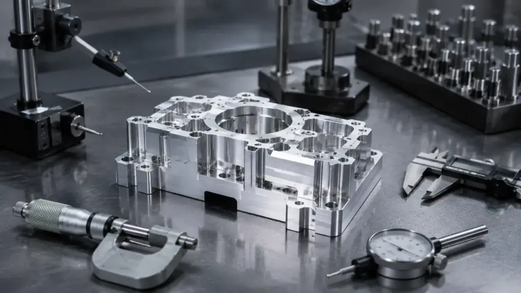
Tight tolerances increase cost because they require more than slower cutting.
Additional cost may come from:
- Detailed engineering review
- More rigid or custom fixtures
- Reduced material-removal rates
- Dedicated finishing tools
- Tool-life control
- Additional setups or reduced setup count through multi-axis machining
- More frequent in-process inspection
- CMM programming and measurement
- 100% inspection
- Post-treatment verification
- Higher scrap and rework risk
The best cost-control strategy is not to remove every tight tolerance. It is to apply precision only where it protects product function.
A drawing containing two clearly identified critical features is easier to plan and quote than a drawing that applies ±0.01 mm to every dimension without functional justification.
How to Evaluate a Precision CNC Milling Supplier?
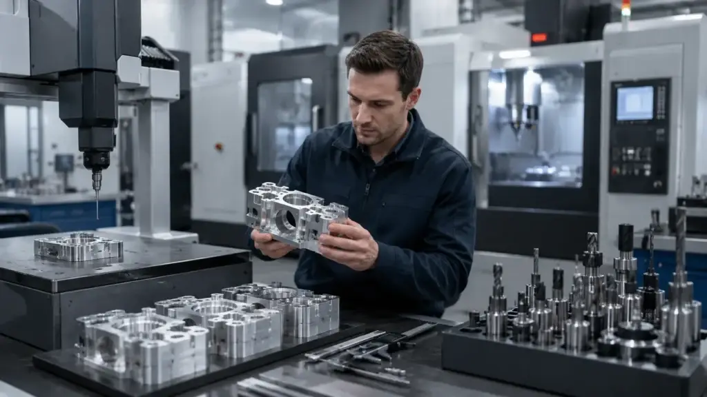
A supplier’s precision claim should be supported by process and inspection evidence.
Ask the following questions:
- Does the stated tolerance apply to one feature or the complete part?
- Which materials and part sizes are covered?
- Is the figure based on machine positioning or finished-part capability?
- How are critical datums and setups planned?
- How is tool wear monitored?
- Which dimensions are inspected during production?
- What equipment is used for GD&T verification?
- Can the supplier provide FAI or CMM reports?
- Are measuring instruments calibrated and controlled?
- How are nonconforming parts handled?
- Are material and batch records traceable?
- Are critical dimensions rechecked after surface treatment?
A capable precision CNC milling supplier should be able to explain how the tolerance will be produced and verified—not only state that it is achievable.
How SinoRise Supports Precision CNC Milling Projects?
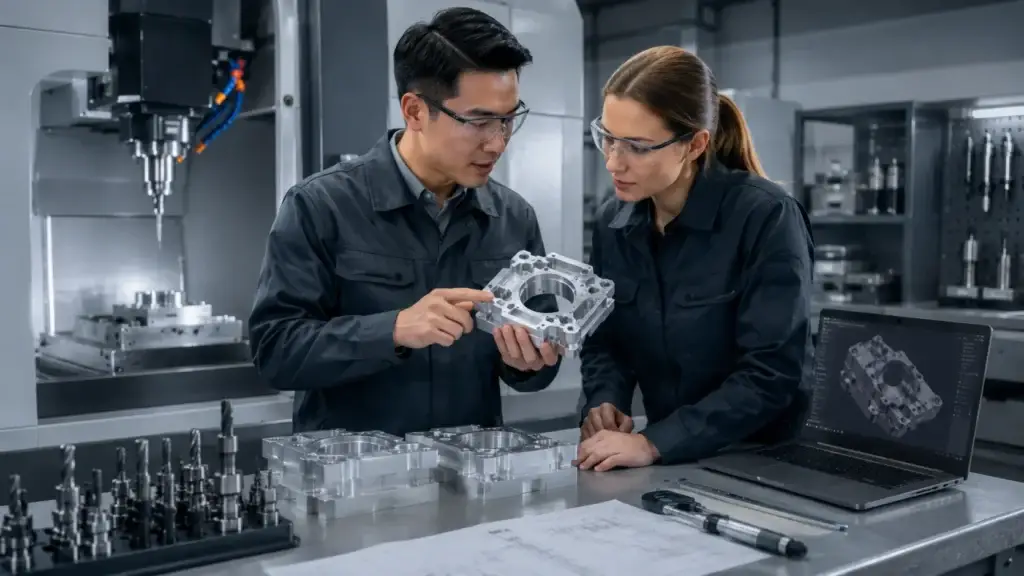
SinoRise approaches precision milling as a connected process involving drawing review, machining strategy, inspection planning and production feedback.
Before production, the engineering team reviews:
- Material and geometry
- Critical tolerances
- Datum structure
- Number of setups
- Tool access
- Fixture requirements
- Surface finishing
- Inspection and reporting needs
SinoRise operates more than 40 precision machining machines and uses inspection equipment including 2.5D measuring systems, digital height gauges and CMM equipment. Production is managed under an ISO 9001 quality system, with a focus on components for medical equipment, UAVs, semiconductor systems, robotics, optical instruments and automotive or motorcycle applications.
For prototypes and small batch CNC machining, the process can include first-article verification before the remaining quantity is released. For repeat production, critical dimensions can be monitored at planned intervals to identify tool wear or dimensional drift.
The objective is not to promise one tolerance for every part. It is to establish a manufacturing and inspection plan appropriate to the specific component.
Frequently Asked Questions
What tolerance can precision CNC milling achieve?
The achievable tolerance depends on the feature, material, part size, geometry, setup and measurement method. General features may use wider machining tolerances, while selected critical features may achieve ±0.01 mm or tighter after engineering review.
Is ±0.01 mm possible with CNC milling?
It can be possible on suitable features and parts. The supplier must evaluate material behavior, tool access, fixture rigidity, thermal conditions and inspection capability before confirming it.
What affects CNC milling accuracy most?
The main influences include machine condition, fixture stability, datum strategy, tool deflection, tool wear, material stress, temperature and the number of setups.
What is the difference between FAI and final inspection?
FAI verifies the initial production setup and confirms that the planned process can meet the drawing. Final inspection verifies completed parts before shipment. In-process checks are still required to control variation between these stages.
When is CMM inspection required?
CMM inspection is valuable for complex GD&T, positional relationships, profiles and features located on different faces. Simpler dimensions may be measured more efficiently with micrometers, gauges or optical equipment.
Is 100% inspection always necessary?
No. Inspection frequency should be based on feature risk, tolerance, process stability, quantity and customer requirements. Safety-critical or unstable features may require 100% inspection, while stable general features may use sampling.
Does anodizing affect CNC tolerances?
Anodizing adds a controlled surface layer and can affect precision fits, holes and threads. Critical dimensions should specify whether they apply before or after anodizing and whether masking or post-treatment inspection is required.
How does 5-axis machining improve accuracy?
Five-axis machining can reduce the number of setups required for multi-face parts. Fewer datum transfers can improve the positional relationship between features, although the final result still depends on programming, fixtures and inspection.
What quality documents should a buyer request?
Depending on the project, useful documents include an FAI report, dimensional report, CMM report, material certificate, surface-treatment certificate and lot-traceability record.
Request a Precision CNC Milling Review
Send SinoRise your 3D model, 2D drawing, material, quantity, critical tolerances, surface treatment and inspection requirements.
Our team will review the machining route, datum strategy, inspection method and process-control requirements before quotation.
Upload your drawing to request a precision CNC milling and DFM review.