

CNC Turned Aluminum Valve Disc
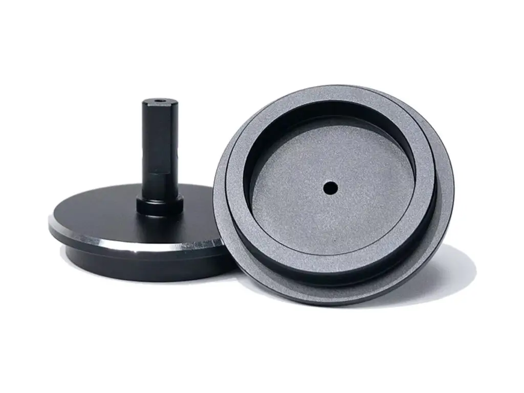
Valve discs turned from 6061-T6 bar, with a seat face lapped flat to 0.005 mm at Ra 0.4 µm, a stem held to h7 and square to the seat within 0.01 mm, a seat angle of 30° to 45° held to ±0.25° and disc thickness to ±0.02 mm. The edge is chamfered 30° so the disc enters its guide without shaving the bore.
- Seat Face Lapped 0.005 mm
- Stem Guided to 0.01 mm
- Edge Chamfer 30°
- Disc Thickness ±0.02 mm
*Send the seat drawing and the working pressure. The seat angle and the disc thickness are set by the seat geometry, and a disc machined to a nominal angle will only seal on one line.
Valve Disc Overview
A valve disc closes against a seat, and it seals on a narrow band rather than on its whole face. That band has to be flat, square to the stem and at the right angle, or the disc leaks at one point and hammers at another.
The disc is turned with the seat face oversize, the stem is turned and the angle is cut, then the seat face is lapped on a flat plate. The stem is checked for squareness to the lapped face, not the other way round, because the face is the sealing datum.
6061-T6 Aluminium Bar
6061-T6 is used for low-pressure water and air valves because it is light, machines to a fine seat and hard anodizes to a wear surface. It is not suitable for steam or aggressive chemicals, where the oxide layer breaks down.
6082-T6 or 316L Stainless
6082 is the European equivalent for general valve bodies. 316L is chosen for water with chlorides and for food duty, where an anodized aluminium seat would corrode and contaminate the flow.
Aluminium is right for air and clean water at moderate temperature; anything hotter or more aggressive moves the disc to stainless, whatever the cost.
Valve Disc Specifications
Turning and lapping data for valve discs, with the seat, stem and angle values that decide whether the valve seals.
| Specification | Machining Data | Specification | Machining Data |
|---|---|---|---|
| Product | Valve Disc / Poppet Disc | Machining Process | CNC Turning, Lapping, Chamfering |
| Material | 6061-T6 Aluminium Bar | Diameter Range | Ø 25 – 200 mm |
| Seat Face | Flatness 0.005 mm, Ra 0.4 µm | Disc Thickness | ±0.02 mm |
| Stem Diameter | Ø 6 – 30 mm, h7 | Stem Squareness | 0.01 mm to the Seat Face |
| Seat Angle | 30° – 45° ±0.25° | Concentricity | Stem to Seat OD 0.01 mm |
| Edge Chamfer | 30° × 1 mm | Surface Finish | Ra 0.4 µm Seat, Ra 1.6 µm Body |
| Customization | O-ring Groove, Guide Bands, Hard Anodizing | Lead Time | 5 – 7 Days Sample, 10 – 14 Days Batch |
| Inspection | Optical Flat and Light Band, Air Gauge Stem, CMM Squareness | Packing | Seat Face Protected, Individually Boxed, VCI |
Key Features of Our Valve Discs
Lapped seat, stem square to the face.
Seat Face Lapped to 0.005 mm
Lapping on a flat plate produces a sealing band that closes evenly, instead of a turned face that touches on one side only.
Stem Square to the Seat Face
The stem is checked against the lapped face within 0.01 mm, so the disc seats flat when the actuator pushes it straight.
Seat Angle Held to ±0.25°
The angle is turned with a form tool and checked on an optical comparator, because a quarter of a degree changes where the disc contacts the seat.
Chamfered Entry Edge
A 30° chamfer lets the disc enter the guide without shaving a burr off the bore, which is a common cause of a new valve sticking.
Disc that has to seal on a narrow band?
Surface Finishes for Valve Discs
The seat face stays bare and lapped; the body can be coated for wear and corrosion.
| Finish | Main Purpose | Finish | Main Purpose |
|---|---|---|---|
| Hard Anodizing | Wear resistance on the seat and the guide | Type II Anodizing | Corrosion protection on the body |
| Masked Seat Face | Keeps the lapped face flat and uncoated | Bead Blasting | Even matte before dye |
| Laser Marking | Seat size and flow direction | PTFE Coating | Low friction on a dry-running stem |
*Hard anodizing adds 25 to 50 µm and would destroy a lapped seat. The seat is masked, or the disc is machined undersize and lapped after coating.
Put your CNC milling parts into production today
All information and uploads are secure and confidential.
Trusted for Precision CNC Machined Components
Supporting OEM projects with accurate machining, flexible production, and reliable component quality.
Trusted for Precision CNC Milling.
Turning Process for Valve Discs
The seat face is lapped after the stem is turned, so the disc closes flat on its seat instead of rocking on a high spot.
01. Seat and Pressure Review
Check the seat geometry, the working pressure and the actuator force, then confirm the seat angle and the disc thickness before turning.
02. Turn Body and Stem
Turn the outside, the stem and the seat angle in one operation, leaving 0.05 mm on the seat face for lapping.
03. Cut the Chamfer and Groove
Cut the entry chamfer and any O-ring groove, then deburr the stem end and the groove edges before lapping.
04. Lap the Seat Face
Lap the seat face on a flat plate to 0.005 mm, checking with optical flat and light band, then clean the part ultrasonically.
05. Check Squareness and Coat
Check stem squareness to the lapped face, mask the seat, anodize and re-check the stem diameter before packing.
Send the seat drawing and the actuator force, and we will quote discs with the seat lapped and the stem square to it.
Valve Disc FAQs
0.005 mm, checked with an optical flat and light band. That is what allows the disc to seal on a narrow band without a soft gasket.
Because the seat face is what seals. If the stem is used as the datum, the lapped face can end up out of square and the disc will leak no matter how straight the stem is.
Yes, with the seat masked. If a coated seat is required, the face is machined undersize, coated and then lapped back to flat, which is a slower and more expensive route.
±0.25° on the included angle, checked on an optical comparator. The seat in the body has to be matched to the same angle for the contact band to be narrow.
On a long stroke, yes. A guide band keeps the disc concentric in the bore so the seat band stays even, and it is machined as part of the stem to 0.01 mm.
Up to about 16 bar in clean water or air at moderate temperature. Above that the seat deflects and the disc is made in stainless or bronze.
Other CNC Machined Mechanical Components
Explore additional precision CNC machined components manufactured for OEM applications and customized production needs.
316L stainless fluid manifold blocks machined from solid with flat port faces to 0.02 mm, drilled galleries cleared by borescope.
Five-axis milled aluminium curved sensor brackets with swept mounting pads, blended fillets and 0.03 mm pad flatness for robot.
Precision CNC machined aluminum robot joint housings for arm segments and joint modules.
Precision CNC machined aluminum robot joint housing flanges.
Custom CNC machined aluminum intake manifolds for automotive and motorsport builds.
Get high‑quality machined parts in as fast as 4 days with our expanded automated CNC milling!