


Home / CNC-Machining / CNC-Turning / CNC Turned Aluminum Heat Sink Shaft
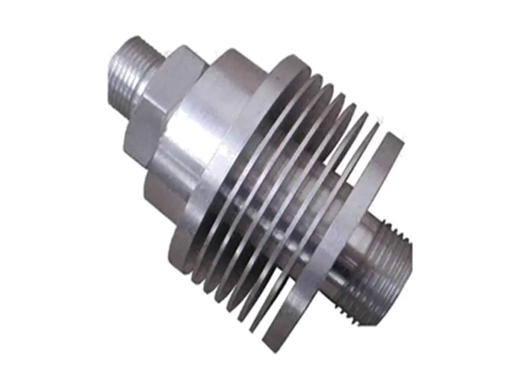
CNC turned 6061-T6 aluminium heat sink shaft with machined fins and threaded ends

CNC Turned Aluminum Heat Sink Shaft

6061-T6 aluminium heat sink shafts turned with six to forty fins at a pitch held to ±0.05 mm, a ground journal to h6 with runout under 0.01 mm and threads at both ends coaxial to the journal within 0.03 mm. Used where a shaft has to carry heat out of a housing as well as locate a bearing.

*Tell us the heat load and the airflow, not just the fin count. Fin pitch has to suit the air moving past it, and fins that are too close together in still air dissipate less than a plain shaft.

Heat Sink Shaft Overview

A finned shaft does two jobs: it locates a rotating part and it moves heat out of a housing. Both depend on the same axis, so the fins, the journal and the threads all have to be turned from one datum.

The shaft is turned with the fins grooved from one end, then the journal is ground between centres so it is true to the fin stack. Threads are cut last and checked for coaxiality, and any anodizing is done with the journal masked.

Workshop production of a stainless steel stepped axle pin
6061-T6 aluminium round bar stock for CNC turning

6061-T6 Aluminium Bar

6061 has about 170 W/m·K thermal conductivity and machines cleanly into thin fins, which is why it is the default for a finned shaft. Copper would conduct better but is three times the weight and does not hold a thin fin as well.

7075-T6 aluminium round disc blank for CNC machining

7075-T6 or Copper Alloy

7075 is used where the shaft is also highly loaded and the fins still need to be thin. A copper alloy is chosen for the highest heat flux, accepting the weight and the cost of machining it.

Conductivity is the reason to use aluminium at all: if the shaft is not actually removing heat, a plain turned shaft is cheaper and stronger.

Heat Sink Shaft Specifications

Turning and grinding data for finned shafts, with the fin, journal and coaxiality values that decide whether the part cools and turns true.

SpecificationMachining DataSpecificationMachining Data
ProductFinned Heat Sink ShaftMachining ProcessCNC Turning, Fin Grooving, Threading, Grinding
Material6061-T6 Aluminium BarShaft Diameter15 – 90 mm
Length40 – 400 mmFin Count6 – 40 Fins
Fin Thickness1 – 4 mmFin Pitch±0.05 mm
Journal DiameterØ 10 – 60 mm, h6 GroundJournal Runout0.01 mm
ThreadsM8 – M40 Both EndsThread Coaxiality0.03 mm to the Journal
Surface FinishRa 1.6 µm Fins, Ra 0.4 µm JournalAnodizingType II 10 – 20 µm
CustomizationCross Holes, Keyway, Flats, Integral CollarLead Time6 – 8 Days Sample, 13 – 17 Days Batch
InspectionMicrometer Journal, Runout on Centres, Fin Pitch Gauge, Thread GaugesPackingFin Guard, Individually Bagged, Carton

Key Features of Our Finned Shafts

Fins from one datum, journal ground to h6.

Fin Pitch Held to ±0.05 mm

Fins are grooved from a single stop on the turret, so the pitch is even along the whole stack and the airflow between them is uniform.

Journal Ground Between Centres

The journal is ground after turning with the shaft on centres, holding runout to 0.01 mm so the bearing does not preload the fin stack.

Fin Roots Deburred

Every fin root is deburred, because a burr at the root blocks the air path exactly where the heat has to leave the shaft.

Threads Coaxial to the Journal

Both threads are cut from the ground journal as the reference, holding coaxiality to 0.03 mm so a coupling does not whip at speed.

Shaft that has to carry heat as well as load?

Surface Finishes for Heat Sink Shafts

A coating that insulates defeats the purpose, so the finish is thin and the journal is masked.

FinishMain PurposeFinishMain Purpose
Type II AnodizingCorrosion protection without insulating the finsBlack DyeEmissivity for radiant heat dissipation
Masked JournalKeeps the bearing fit at h6Hard AnodizingWear resistance on a shaft that is handled
Bead BlastingIncreases surface area slightly and hides marksBare Machined FinsMaximum conductivity where the shaft is earthed

*Anodizing is a thermal barrier. Fins are coated thin, 10 to 20 µm, and a shaft that relies on conduction into a housing is left bare at the interface.

logo

Put your CNC milling parts into production today

All information and uploads are secure and confidential.

Trusted for Precision CNC Machined Components

Supporting OEM projects with accurate machining, flexible production, and reliable component quality.

Mechanical Equipment Customer
Bearing temperature dropped 14 °C after we swapped to the finned shaft.

Industrial Components Buyer
The journal ran true, so the bearing is quiet at full speed.

Equipment Manufacturer
Fins are even, and the airflow between them is uniform along the stack.

OEM Customer
OEM Customer
Threads took the coupling without runout, with no vibration at 3,000 rpm.

Automation Industry Customer
The customized machining solution provided the dimensional accuracy required for our rotating equipment components.
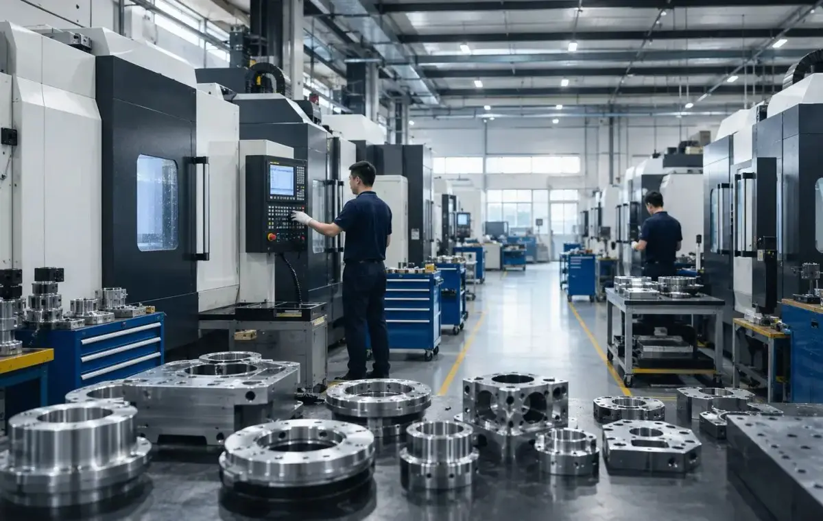
Trusted for Precision CNC Milling.

Turning and Grinding Process

Fins are grooved at a constant pitch from one datum, so the shaft dissipates heat evenly instead of running hot at one end.

01. Thermal and Fit Review

Check the heat load, the airflow and the bearing fit, then decide the fin pitch and whether the journal can be ground after anodizing.

02. Turn the Body and Fins

Turn the body, groove the fins from one stop with a profile tool and leave the journal oversize for grinding.

03. Thread Both Ends

Cut both threads from the same datum, leaving the journal as the reference diameter so the threads run coaxial to it.

04. Grind the Journal

Mount between centres and grind the journal to h6, checking runout to 0.01 mm and the surface finish to Ra 0.4 µm.

05. Mask, Anodize and Pack

Mask the journal, anodize the fins, then check the journal and thread gauges again and fit a fin guard before bagging.

Send the heat load and the bearing fit, and we will quote the shaft with the fin pitch and journal finish matched to the duty.

Heat Sink Shaft FAQs

Between eight and twenty for natural convection, and up to forty where air is forced through the stack. Beyond that the gaps close up and the airflow stalls.

A thin Type II coat reduces conduction slightly but adds emissivity, which usually helps in still air. On a conduction path the interface is masked and left bare.

Because a turned journal holds about 0.02 mm runout, and a bearing at 3,000 rpm feels that. Grinding brings it to 0.01 mm with a finer finish.

Yes, straight fins can be milled, but grooving on the lathe is faster and leaves a better root radius, which matters for fatigue in a rotating shaft.

1 mm at 3 mm pitch in 6061. Thinner fins deflect under the tool and the pitch drifts, so they are cut in two passes with a support sleeve.

Yes, if the fins are grooved symmetrically and the shaft is turned between centres. Asymmetric grooving is what bends a thin shaft.

Other CNC Machined Mechanical Components

Explore additional precision CNC machined components manufactured for OEM applications and customized production needs.

316L stainless fluid manifold blocks machined from solid with flat port faces to 0.02 mm, drilled galleries cleared by borescope.

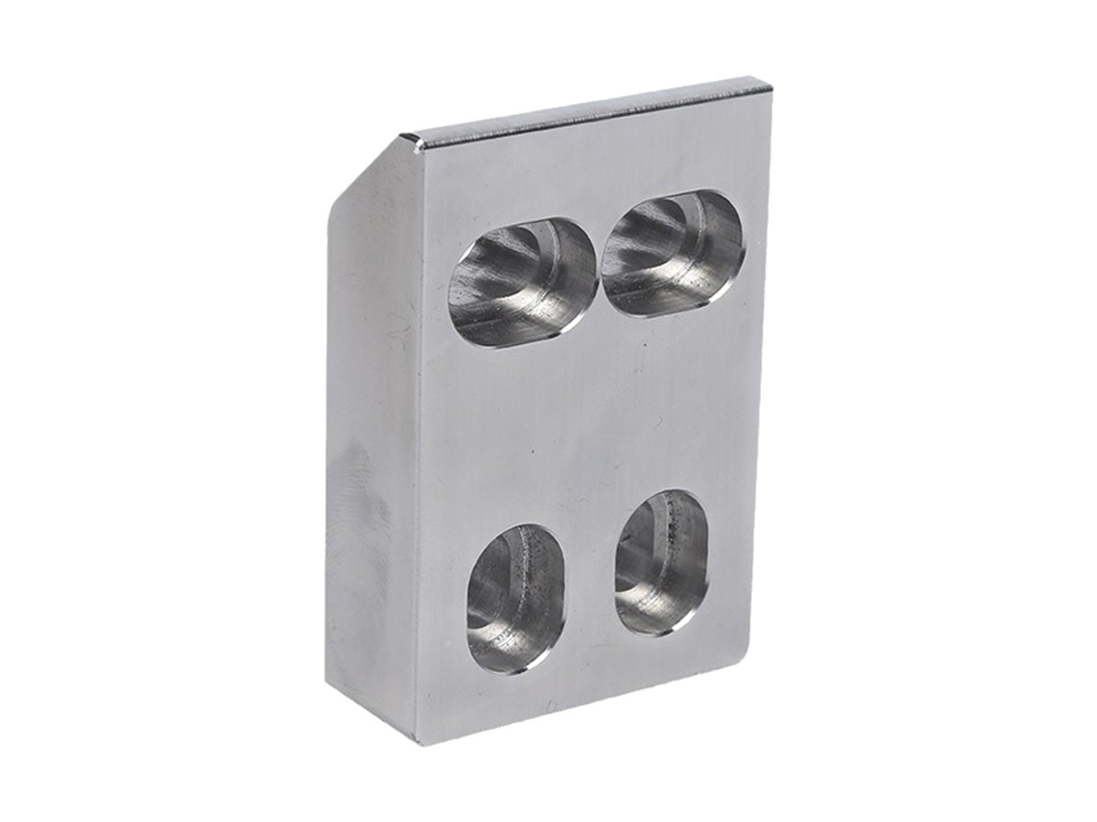
Five-axis milled aluminium curved sensor brackets with swept mounting pads, blended fillets and 0.03 mm pad flatness for robot.

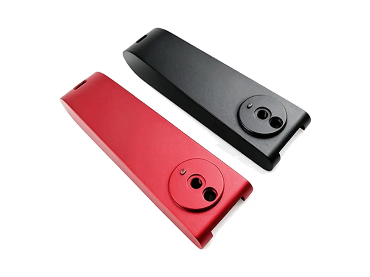
Precision CNC machined aluminum robot joint housings for arm segments and joint modules.

Precision CNC machined aluminum robot joint housing flanges.

Custom CNC machined aluminum intake manifolds for automotive and motorsport builds.

Get high‑quality machined parts in as fast as 4 days with our expanded automated CNC milling!

Scroll to Top