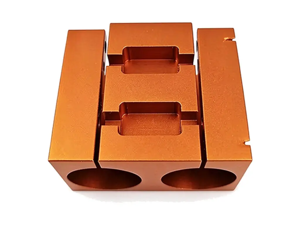


CNC Milled Aluminum Split Clamping Block
CNC milled aluminium split clamping blocks for linear shafts, guide rods and spindle mounts, machined from 6061-T6 plate with the bore held to H7 and the two bores coaxial within 0.02 mm. The block is bored as a solid piece and split afterwards so both halves match across the joint.
- Matched Halves, Bore to H7
- Sawn Split With Even Gap
- Orange or Black Anodizing
- Bore Coaxial to 0.02 mm
*Give us the shaft diameter and its tolerance, not just the nominal size. A ground shaft at the low end of h6 needs a different bore than a drawn shaft at the top of its band.
Aluminum Split Clamping Block Overview
A split clamp holds a shaft by friction, so the bore has to be round and the two halves have to match. If the block is split first and bored afterwards, the halves no longer line up and the clamp pinches the shaft on one side, which shows up as a stick-slip motion on a linear axis.
The block is machined as one piece, bored and reamed to size, then sawn through on a wire or a slitting saw with a controlled gap. Screw holes are drilled before the split so the thread stays aligned, and the halves are numbered and kept together through anodizing and packing.
6061-T6 Aluminium Plate
6061-T6 is used for clamp bodies because it is stiff enough to hold a bore under screw load and machines without leaving a burr inside the split. It anodizes evenly, which matters when several clamps on one machine are colour coded.
7075-T6 for Higher Clamp Load
7075-T6 is chosen when the clamp carries a heavy rod or is tightened hard, because its higher yield strength keeps the bore from going out of round at the screw. It anodizes to a deeper colour and costs more per block.
The clamp material is set by the screw load rather than the shaft size. A 40 mm bore with two M6 screws will deform a 6061 block before it slips on the shaft.
Split Clamping Block Specifications
Milling and anodizing data for split clamps, with the bore, split gap and coaxiality values that decide grip.
| Specification | Machining Data | Specification | Machining Data |
|---|---|---|---|
| Product | Split Shaft Clamping Block | Machining Process | CNC Milling, Saw Split, Matched Pair Boring |
| Material | 6061-T6 Aluminium Plate | Bore Tolerance | H7 (+0.021 / 0 on 20 mm Bore) |
| Bore Range | 8 – 40 mm | Bore Coaxiality (Two Bores) | 0.02 mm |
| Block Size | 30 × 30 × 20 mm to 120 × 80 × 60 mm | Split Gap | 1.5 – 3 mm After Sawing |
| Clamp Screw | M4 to M10, 2 or 4 per block | Bore to Base Squareness | 0.03 mm |
| Wall Around Bore | Minimum 3 mm at the thinnest point | Surface Finish | Ra 1.6 µm Bore, Ra 3.2 µm Body |
| Split Method | Saw Cut, Then Deburr and Ream to Size | Anodizing | Type II 15 – 20 µm, Black or Orange |
| Customization | Bore Count, Screw Pattern, Mounting Flange, Colour | Lead Time | 6 – 8 Days (Sample), 12 – 16 Days (Batch) |
| Inspection | Bore Plug Gauge, Coaxiality on CMM, Gap Check | Packing | Halves Kept Paired, Bagged, Carton |
Key Features of Our Split Clamping Blocks
Bored as one piece, split afterwards, so the two halves close on the same circle.
Bored Before the Split
The bore is finished while the block is still solid, so both halves share one circle and the joint does not step when the screws are tightened.
Controlled Split Gap
The saw cut is set to a 1.5 to 3 mm gap, which leaves enough travel to close on the shaft without bottoming the halves against each other.
Numbered Matching Halves
Each pair is marked before anodizing and packed together, so a block is never assembled from two halves that were machined separately.
Screw Holes Drilled Before Splitting
Clamp screw holes and counterbores are cut before the split, which keeps the thread square to the joint and stops the screw from binding as the gap closes.
Need a clamp that grips without marking the shaft?
Surface Finishes for Split Clamping Blocks
Anodizing builds thickness inside the bore as well as outside, so the finish is agreed before the bore is sized.
| Finish | Main Purpose | Finish | Main Purpose |
|---|---|---|---|
| Type II Anodizing | Colour coding and wear resistance on the clamp body | Hard Anodizing | Wear face where the block is adjusted often |
| Bead Blasting | Even matte before dyeing so the colour reads uniform | Laser Marking | Bore size and pair number on the side face |
| Chromate Conversion | Conductive finish when the block is part of a ground path | Assembly Lubricant | Dry-film lubricant on the bore for sliding shafts |
*Type II anodizing adds 7 to 10 µm per surface, which closes a 20 mm bore by up to 0.02 mm. Bores that must stay H7 after anodizing are machined 0.02 mm oversize and reamed after the dye.
Put your CNC milling parts into production today
All information and uploads are secure and confidential.
Trusted for Precision CNC Machined Components
Supporting OEM projects with accurate machining, flexible production, and reliable component quality.
Trusted for Precision CNC Milling.
Milling Process for Split Clamping Blocks
The two halves are bored as one block and split afterwards, so the bore closes on the shaft without a step at the joint.
01. Shaft and Load Review
Check the shaft tolerance, the screw size and the clamp load against the wall thickness around the bore, and confirm the split direction before programming.
02. Block Preparation
Square the 6061 plate to size, face both reference faces and mark the datum corner, since the bore and the screw pattern are both programmed from those faces.
03. Bore, Ream and Drill
Drill, bore and ream the shaft bore to H7, then drill and tap the clamp screws and cut the counterbores while the block is still one piece.
04. Split and Deburr
Saw the split to the specified gap, deburr both cut faces by hand and check that the halves close without a step at the joint.
05. Anodize, Gauge and Pack
Anodize to colour, ream the bore if the drawing calls for a post-anodize fit, gauge the bore, then bag each numbered pair together.
Send the shaft diameter, the screw size and the colour you need, and we will quote the clamp with the bore and split gap defined.
Split Clamping Block FAQs
Not if the bore is finished to Ra 1.6 µm and the screws are tightened to the specified torque. Heavier marks come from overtightening or from a bore that is out of round, both of which we control at the boring step.
Yes, and the two bores are machined in one set-up so they stay coaxial and parallel within 0.02 mm. Blocks bored in two set-ups are the usual reason a twin-rail axis binds.
1.5 to 3 mm for bores up to 40 mm. The gap has to be wide enough to close on the shaft but narrow enough that the halves do not touch before the clamp is tight.
Yes, by up to 0.02 mm on a 20 mm bore. When the drawing specifies H7 after finishing, the bore is machined oversize and reamed after anodizing, and the fit is checked with a plug gauge.
Yes. A flange with counterbored holes is milled into the base in the same set-up as the bore, so the mounting face stays square to the shaft axis within 0.03 mm.
Anything from one sample to a few thousand. Above about 200 pieces the block is cut from extruded bar rather than plate, which lowers the material cost and shortens the cycle.
Other CNC Machined Mechanical Components
Explore additional precision CNC machined components manufactured for OEM applications and customized production needs.
316L stainless multi-port valve bodies machined from solid, port faces flat to 0.02 mm and cross-drilled galleries pressure.
Custom five-axis CNC milled 316L stainless steel mixing impellers for agitators and reactors.
Precision CNC machined stainless steel control valve bodies with lapped sealing faces and gauged ports.
Custom CNC machined steel hydraulic connectors and adapters for 350 bar systems.
Custom CNC machined aluminium brake booster check valve bodies for motorcycles and automotive systems.
Get high‑quality machined parts in as fast as 4 days with our expanded automated CNC milling!