

CNC Turned Brass Flanged Bushing
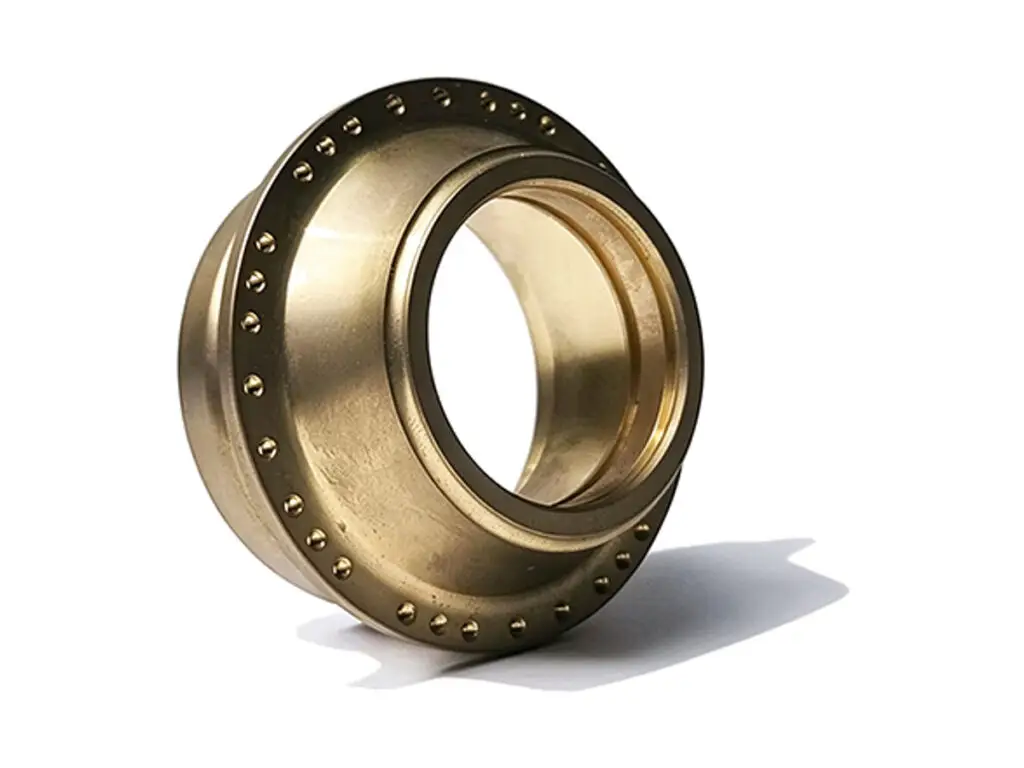
CNC turned brass flanged bushings for steering pivots, swingarm linkages and suspension joints, machined from C36000 free-cutting brass with the bore held to H7 and the flange square to the bore axis within 0.02 mm. The flange carries the axial load, the bore carries the pin, and both are cut from the same bar without a re-chuck.
- Bore Held to H7
- Flange Square to 0.02 mm
- Free-Cutting C36000 Brass
- One-Set-Up Turning
*Send the pin diameter and the housing bore together. The running clearance is set by the pair, and a bushing that is correct on its own will still seize if the housing is reamed oversize.
Brass Flanged Bushing Overview
A flanged bushing is a wear part, so the numbers that matter are the ones that decide how it wears: bore clearance, wall thickness and whether the flange sits flat against the housing face. Brass is used because it runs against steel without galling and can be replaced before the pin is damaged.
The bushings are turned from bar, bored and grooved, then parted and faced so the flange face is square to the bore rather than to the sawn end. An internal lubrication groove is cut with a form tool at a constant depth, which keeps the oil film even around the circumference instead of pooling on one side.
C36000 Free-Cutting Brass
C36000 machines at high speed with short chips and holds a fine bore without a reamer, which is why it is the default for bushings that are made in quantity. Its lead content gives the dry-running film that protects a steel pin during start-up.
C93200 Bearing Bronze
C93200 is specified when the bushing has to run under load with poor lubrication, for example a suspension pivot that sees shock loads. It is slower to machine and costs more per part, but the tin and lead content gives a longer wear life than brass.
Choose brass for light pivots and bronze for load-bearing joints. Both are turned the same way, so the decision is made on the wear duty rather than on the machining route.
Brass Flanged Bushing Specifications
Dimensional data for turned flanged bushings, with the bore and flange tolerances that decide fit in the housing.
| Specification | Machining Data | Specification | Machining Data |
|---|---|---|---|
| Product | Flanged Pivot Bushing | Machining Process | CNC Turning, Second-Op Face and Bore |
| Material | C36000 Free-Cutting Brass | Bore Tolerance | H7 (+0.021 / 0 on 20 mm Bore) |
| Bore Range | 6 – 40 mm | Outside Diameter | IT7, Ground Finish on Request |
| Flange Diameter | 12 – 60 mm | Flange Squareness | 0.02 mm to the Bore Axis |
| Wall Thickness | 1.5 – 6 mm | Concentricity | 0.015 mm Bore to OD |
| Length Range | 5 – 60 mm | Surface Finish | Ra 0.8 µm Bore, Ra 1.6 µm OD |
| Lubrication Feature | Groove, Cross-Hole, Chamfered Oil Pocket | Edge Break | 0.2 mm on Bore Ends, No Burr in Groove |
| Customization | Flange OD, Groove Position, Thread, Marking | Lead Time | 5 – 7 Days (Sample), 10 – 14 Days (Batch) |
| Inspection | Bore Plug Gauge, Roundness, Squareness on Granite | Packing | Oil-Dipped, Bagged, Carton with Desiccant |
Key Features of Our Turned Brass Bushings
Turned for fit, not just for shape: bore, flange and groove are all referenced to the same axis.
Bore and Flange From One Set-Up
The bore is finished before the part is parted, so the flange face is square to the bore axis within 0.02 mm instead of being faced against a sawn end.
Constant-Depth Oil Groove
The internal groove is cut with a form tool in a single pass, keeping the depth even around the bore so the oil film does not thin on one side of the pin.
Controlled Wall Thickness
Wall thickness is held within 0.1 mm around the circumference, which keeps the press fit uniform and stops the bushing from collapsing when it is installed.
Deburred Bore Ends
Both bore ends are chamfered by 0.2 mm so the pin enters without shaving a burr into the clearance, which is the usual cause of a tight first assembly.
Need bushings that press in without reaming?
Surface Finishes for Brass Flanged Bushings
Brass tarnishes in storage and wears differently once plated, so the finish is chosen with the assembly environment in mind.
| Finish | Main Purpose | Finish | Main Purpose |
|---|---|---|---|
| As Machined | Bare brass bore for oil-impregnated or greased assembly | Nickel Plating | Wear face on visible steering and suspension pivots |
| Vibratory Polishing | Removes turning marks inside the groove | Passivation | Cleans residue after plating on brass assemblies |
| Laser Marking | Size and batch code on the flange face | Clear Lacquer | Slows tarnish when the bushing is stored or shipped |
*Nickel plating adds 5 to 8 µm per surface and closes the bore. Bushings that are plated are bored 10 µm oversize and finished after plating when the clearance is critical.
Put your CNC milling parts into production today
All information and uploads are secure and confidential.
Trusted for Precision CNC Machined Components
Supporting OEM projects with accurate machining, flexible production, and reliable component quality.
Trusted for Precision CNC Milling.
Turning Process for Brass Flanged Bushings
The bore, the flange face and the oil groove are cut in one turning cycle, so the bushing seats square the first time it is pressed in.
01. Fit and Clearance Review
Check the pin diameter, housing bore and running clearance against the drawing. If the clearance is under 0.02 mm on a 20 mm bore, the bore tolerance is tightened before the bar is cut.
02. Bar Selection and Facing
Select C36000 bar close to the flange diameter to minimise wasted material, then face the bar end and centre it so the bore starts concentric.
03. Turn, Bore and Groove
Turn the OD, drill and bore to size, cut the lubrication groove with a form tool, then part off. Groove depth and position are checked on the first part before the cycle is released.
04. Second-Op Facing and Deburring
Face the flange to length, chamfer both bore ends and remove the parting burr by hand so no chip is trapped in the groove.
05. Gauging and Packing
Check the bore with a plug gauge, measure roundness and flange squareness on granite, then oil-dip and bag each bushing so the bore does not corrode in transit.
Send the pin size, housing bore and the load the joint carries, and we will quote the bushing with the clearance already worked out.
Brass Flanged Bushing FAQs
For a steel pin in a brass bushing, 0.02 to 0.05 mm on a 20 mm bore is typical for a slow pivot, and up to 0.08 mm where the joint sees heat. Send the pin tolerance with the drawing and the bore is machined to that clearance rather than to a nominal H7.
Yes, provided the interference is kept between 0.02 and 0.04 mm. Aluminium expands more than brass when the assembly warms up, so a heavy interference can relax and let the bushing spin; we size the OD for the housing material, not just the drawing.
Yes, in a spiral, straight or circumferential pattern, cut with a form tool at 0.5 to 1 mm depth. The groove is kept 1 mm short of each bore end so it does not create an oil leak path at the flange.
Yes. Threaded brass bushings are turned and then threaded in the same cycle, with the thread concentric to the bore within 0.03 mm, which matters when the bushing also acts as a threaded insert.
Bushings are oil-dipped and bagged with desiccant, and clear lacquer is available for parts that sit in stores for months. Lacquer is left off any surface that will be press-fitted, because it changes the interference.
One piece for a sample, with a five to seven day lead time including programming. Batch pricing starts to fall at 100 pieces, and at 500 pieces the bar is cut to the finished length to reduce waste.
Other CNC Machined Mechanical Components
Explore additional precision CNC machined components manufactured for OEM applications and customized production needs.
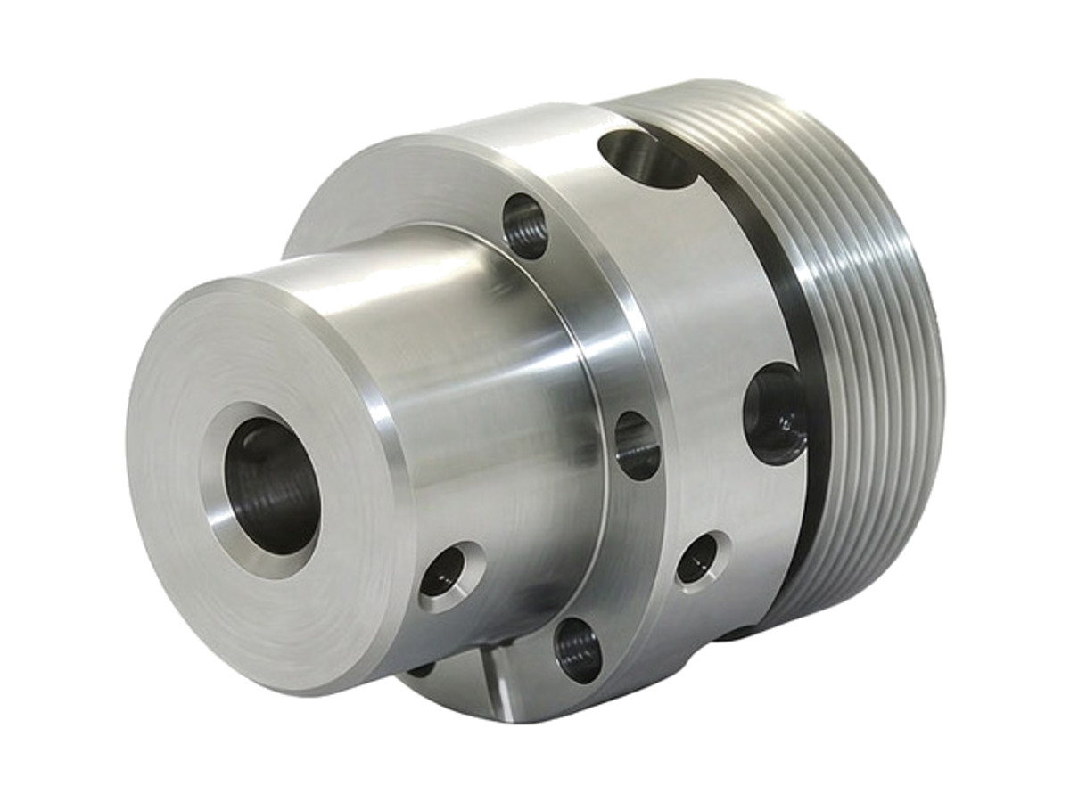
Precision CNC machined stainless steel rotary joint housings for robot arms and fluid transfer.
Custom CNC machined aluminum double tube clamps for motorcycle frames, bicycle builds and hydraulic lines.
Custom CNC machined hardened steel sleeves for robotic joints and motion assemblies.
Custom CNC machined aluminium fuel pump blocks for automotive and motorsport fuel systems.
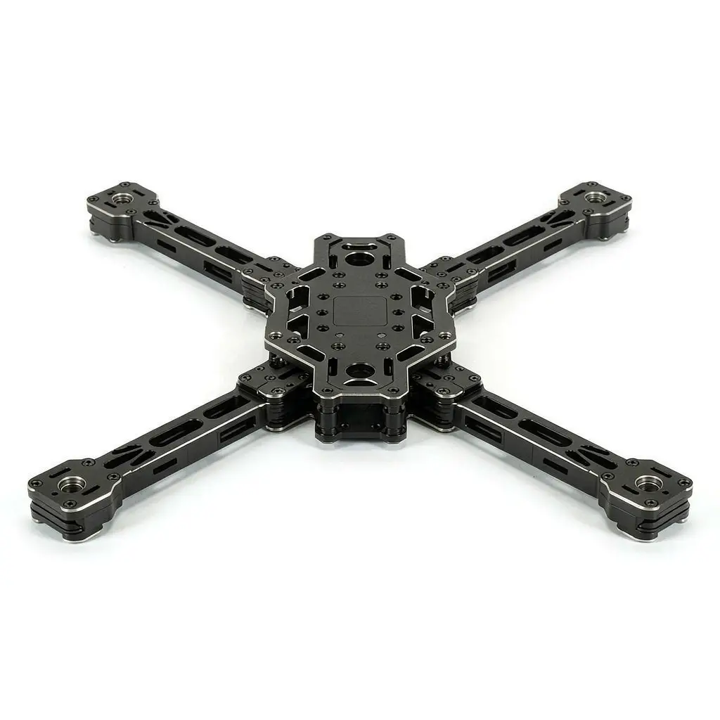
Explore CNC milled UAV frames in 6061 or 7075 aluminum, built for lightweight structures, accurate assembly, component.
Get high‑quality machined parts in as fast as 4 days with our expanded automated CNC milling!