

CNC Machined Robot Joint Housing Flange
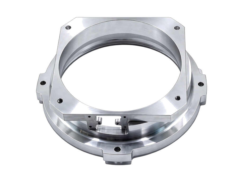
Custom CNC machined aluminum robot joint housing flanges for arm segments and joint modules. Turned and milled from 6061-T6 or 7075-T6 with the bolt circle and the seal groove referenced to the bore, concentric to 0.01 mm and flat to 0.01 mm on the mating face.
- Bolt Circle to ±0.02 mm
- Concentric to 0.01 mm
- Seal Groove Machined
- Serial Marked
*Send the mating flange and the O-ring size, because the groove depth and the bolt circle pitch both decide whether the joint seals before the bolts bottom out.
Robot Joint Housing Flange Overview
A joint flange joins two arm segments and seals the joint at the same time. The bolts hold the load and the O-ring keeps the grease in, and the two only work together if the groove sits at the right depth relative to the mating face.
The flange is turned so the bore, the outer diameter and the face share an axis, then the bolt circle and dowel holes are milled from that bore. The seal groove is cut last, because its depth is measured from the finished face rather than from the rough stock.
6061-T6 Aluminum Bar
6061-T6 round bar is the starting point for housings and discs that are turned before they are milled. The bar is centred once, so the bore, the outer diameter and the flange face share one axis, and the milling that follows is referenced to that axis rather than to an edge.
7075-T6 Aluminum Disc
7075-T6 disc stock is chosen when the part is thin, runs fast or carries a bearing. The higher strength lets a 6 mm web hold a bore without a boss, and the machined surface takes a hard anodized layer without the orange-peel that softer alloys show.
Alloy and groove depth are linked. A soft alloy flange with a shallow groove will creep under bolt load and lose seal pressure, where 7075 holds the groove depth over time.
Robot Joint Housing Flange Specifications
Machining data for joint flanges, agreed against the mating flange and the seal that sits between them.
| Specification | Machining Data | Specification | Machining Data |
|---|---|---|---|
| Product | Robot Joint Housing Flange / Interface Ring | Machining Process | CNC Turning, 4-Axis Milling |
| Material | 6061-T6 / 7075-T6 Aluminum | Typical Tolerance | ±0.02 mm on Bolt Circle, ±0.01 mm on Bore |
| Outer Diameter | 60 – 400 mm | Concentricity | 0.01 mm Bore to Outer Diameter |
| Flange Thickness | 8 – 40 mm | Face Runout | 0.01 mm |
| Bore Diameter | 20 – 250 mm, H7 | Bolt Circle | 4 – 24 Holes, Equally Spaced |
| Seal Groove | O-Ring Groove to ISO 3601 | Surface Finish | Ra 1.6 µm Face, Ra 0.8 Bore and Groove |
| Features | Bolt Circle, Dowel Holes, Seal Groove, Cable Slot | Drawing Format | STEP, STP, IGES, X_T, DWG, DXF, PDF |
| Customization | Bolt Pattern, Groove Size, Cable Slot, Colour | Lead Time | 6 – 10 Days (Prototype), 12 – 20 Days (Batch) |
| Inspection | CMM Bolt Circle and Concentricity, Groove Gauge | Packing | Face Protected, Foam, Carton |
Key Features of Our CNC Machined Joint Flanges
A flange that seals on the O-ring, not on the bolt torque.
Groove Cut from the Finished Face
The seal groove depth is measured from the finished mating face, so the O-ring compression is what the drawing specifies rather than what the rough stock allows.
Bolt Circle from the Bore
Holes are positioned from the bore datum, so the flange centres on the joint axis and the bolts do not pull the joint off centre.
Face Flat to 0.01 mm
The mating face is finished flat to 0.01 mm, which is what lets a face seal hold without a gasket and a heavy bolt torque.
Serial Marked per Joint
Each flange is marked with its joint position, so a replacement can be matched to the arm it came from without measuring.
Joint weeping grease after a rebuild?
Surface Finishes for CNC Machined Joint Flanges
The seal groove is the one area where the finish decides function rather than appearance.
| Finish | Main Purpose | Finish | Main Purpose |
|---|---|---|---|
| As Machined | Bare flange where it is enclosed by the joint cover | Type II Anodizing | Colour and corrosion protection on the visible ring |
| Hard Anodizing | Wear resistance on the locating face | Bead Blasting | Matte face before dyeing |
| Masked Seal Groove | Groove left bare so the O-ring seats on metal | Laser Marking | Serial number and joint position |
*Anodizing inside a seal groove changes its depth and its surface. Grooves are masked before the bath, or cut deeper by the coating thickness where masking is not possible.
Put your CNC milling parts into production today
All information and uploads are secure and confidential.
Trusted for Precision CNC Machined Components
Supporting OEM projects with accurate machining, flexible production, and reliable component quality.
Trusted for Precision CNC Milling.
CNC Machining Process for Robot Joint Flanges
The bolt circle and the seal groove are cut from the bore, so the joint closes on its seal instead of on its bolts.
01. Joint and Seal Review
Check the mating flange, the O-ring size and the bolt circle against the flange thickness, and confirm the groove depth leaves the compression the seal needs.
02. Turning the Ring
Turn the bore, the outer diameter and the mating face in one operation so they share an axis, leaving stock on the face for the finishing cut.
03. Milling the Bolt Circle
Drill, ream and tap the bolt circle and dowel holes from the bore datum, then cut the cable slot where the drawing places it.
04. Groove and Coating
Cut the seal groove from the finished face, mask it, then anodize to the agreed colour and laser mark the joint position.
05. Inspection and Packing
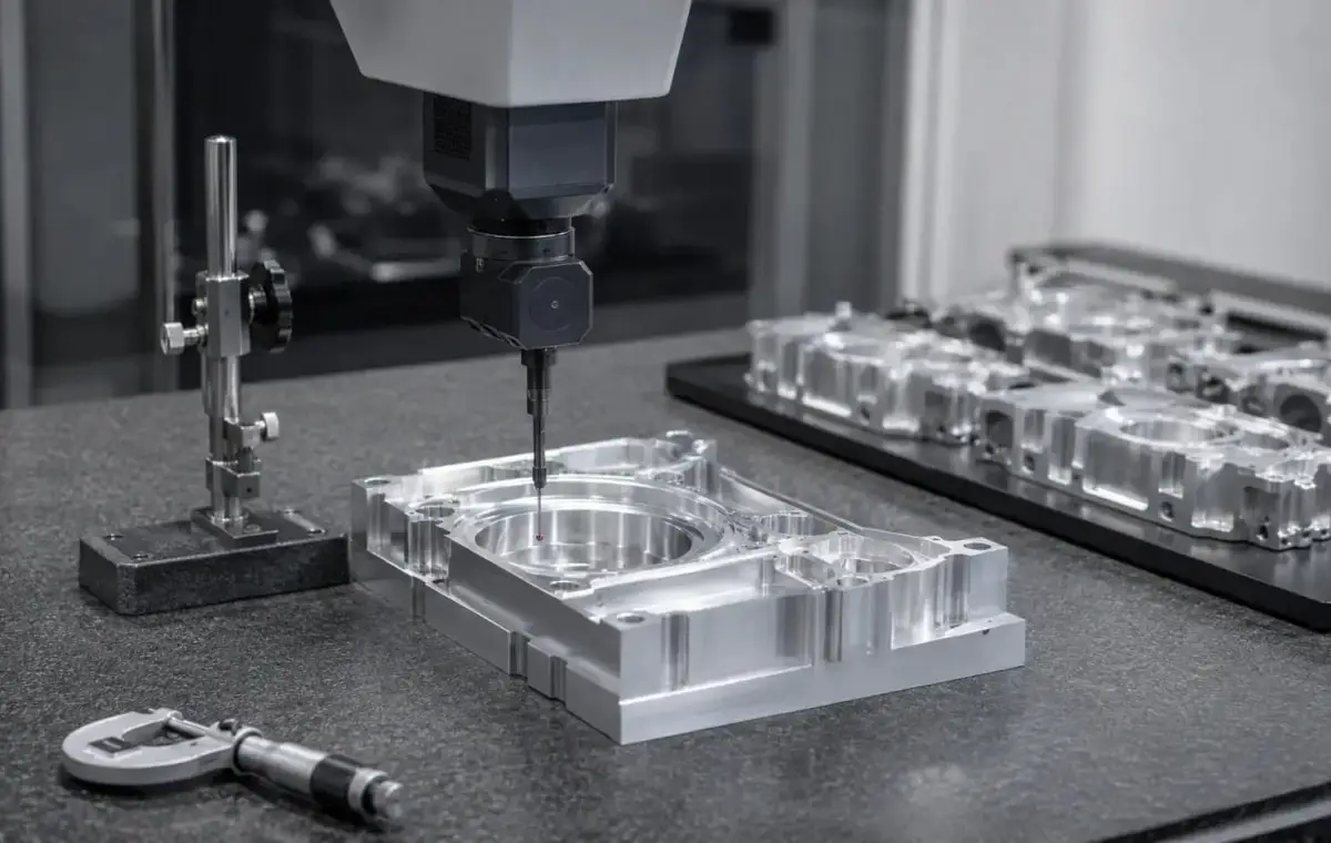
Measure concentricity, face runout and bolt circle position on a CMM, gauge the groove, and pack with the mating face protected.
Have a joint that seeps grease or runs off centre? Send the mating flange and the seal drawing, and we will quote the flange that closes it.
CNC Machined Robot Joint Housing Flange FAQs
The groove depth is what sets O-ring compression, and it is measured from the mating face. Cutting it before the face is finished leaves a depth that depends on how much stock was removed, which is how joints end up leaking or not closing.
Yes, if you send the mating flange or a drawing with the bolt circle and groove. The replacement is programmed from the measured interface, so it drops onto the existing joint without re-drilling.
Holes are positioned to ±0.02 mm from the bore datum, which is tight enough that the bolts do not pull the joint off centre when they are torqued in sequence.
It adds 12 to 18 µm per face, which changes both the depth and the surface. The groove is masked before the bath, or cut deeper by the coating thickness when masking is impractical.
Yes. A cable slot or a drilled pass-through is machined where the drawing places it, with the edges broken so the cable jacket is not cut as the joint rotates.
Six to ten days for a single flange including turning, milling, groove cutting, anodizing and inspection. Repeat orders that reuse the program ship in four to six days.
Other CNC Machined Mechanical Components
Explore additional precision CNC machined components manufactured for OEM applications and customized production needs.
Custom CNC machined aluminium cavity bases for automation and electronic equipment.
Custom CNC machined aluminium brackets for textile machinery and automation frames.
Custom CNC machined steel hydraulic connectors and adapters for 350 bar systems.
Custom CNC machined aluminium manifold blocks for hydraulic and pneumatic circuits.
Get high‑quality machined parts in as fast as 4 days with our expanded automated CNC milling!