

Home / CNC-Machining / CNC-Turning / CNC Turned Aluminum Rod End Joint Fitting
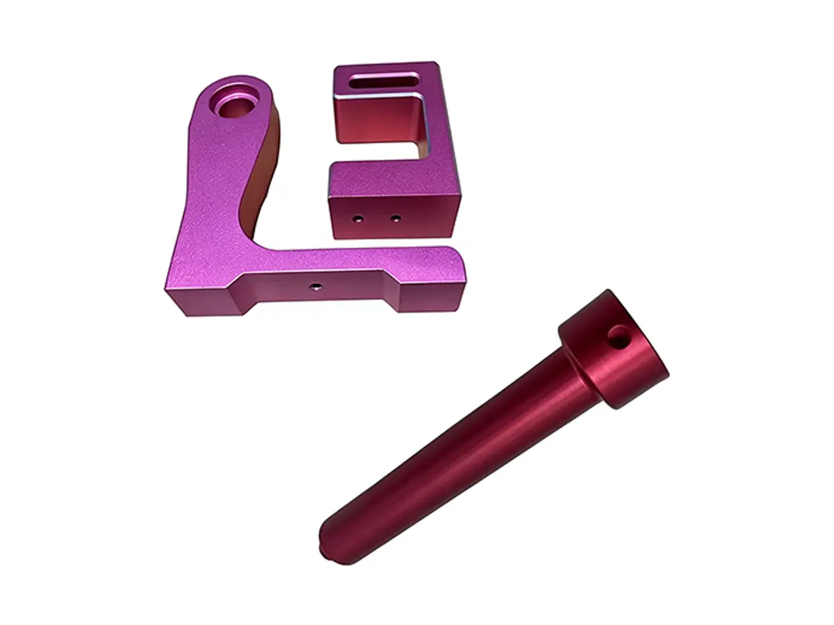
CNC turned anodized aluminium rod end joint fittings with a threaded stem and a bored eye

CNC Turned Aluminum Rod End Joint Fitting

6061-T6 aluminium rod end and clevis fittings turned with an M5 to M20 stem, a cross-drilled eye or a machined fork, thread coaxial to the eye within 0.05 mm and fork faces parallel to 0.03 mm. Anodized in black, red, blue or clear with the threads masked so they still gauge after coating.

*Tell us left or right hand thread and whether a jam nut is supplied. A batch that arrives with the wrong handedness cannot be corrected at assembly, and the pair will not adjust against each other.

Rod End Joint Fitting Overview

A rod end is a small part with a big alignment job: it transfers push and pull along a thread while allowing the joint to rotate. That means the thread and the eye have to share an axis, and the fork faces have to be parallel to the pin.

The stem is turned and threaded first, then the part is held by the thread in a soft collet and the eye is drilled, bored and faced from that axis. Fork fittings are milled from the same set-up so the gap and the faces come out symmetrical.

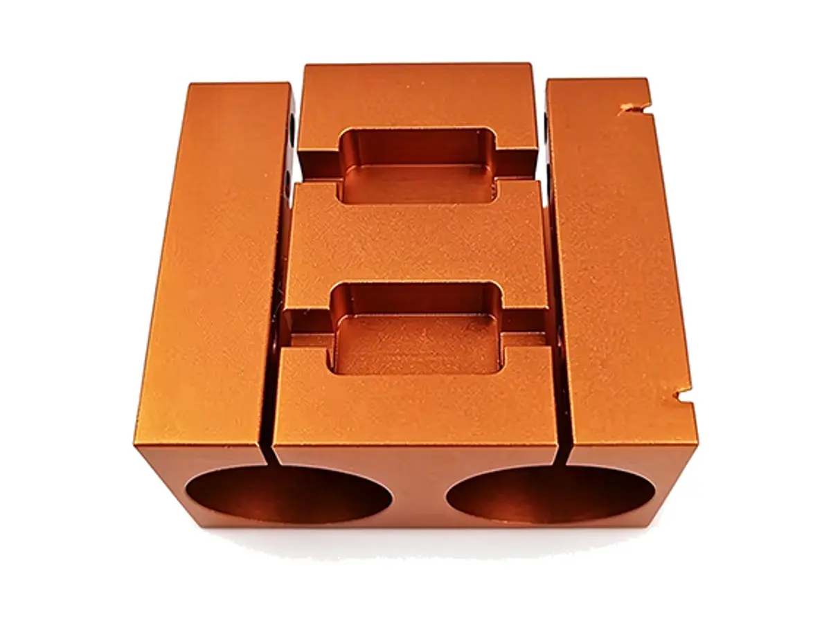
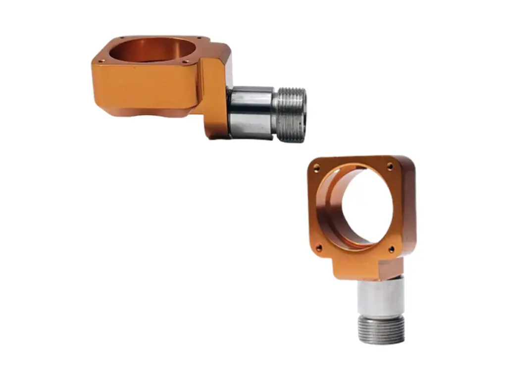
Anodizing of a flanged manifold housing and a cylinder head deck plate
6061-T6 aluminium round bar stock for CNC turning

6061-T6 Aluminium Bar

6061-T6 is used for a light linkage where the rod end is mostly loaded in tension along the stem. It anodizes to a good colour match, which matters when left and right fittings have to be told apart on sight.

7075-T6 aluminium round disc blank for CNC machining

7075-T6 or 304 Stainless

7075-T6 is chosen for a highly loaded linkage where the eye would otherwise ovalise. Stainless is specified for outdoor or marine linkages, where an anodized aluminium eye would wear through at the pin.

Load along the stem suits aluminium; load through the pin, or a wet environment, points to steel or stainless whatever the weight penalty.

Rod End Joint Fitting Specifications

Turning and milling data for rod ends, with the thread, eye and squareness values that decide whether the linkage adjusts and lines up.

SpecificationMachining DataSpecificationMachining Data
ProductRod End Joint Fitting / Clevis FittingMachining ProcessCNC Turning, Milling, Tapping
Material6061-T6 Aluminium BarStem ThreadM5 – M20, Left or Right Hand
Eye BoreØ 5 – 25 mm, H8Fork Gap6 – 30 mm, ±0.03 mm
Eye to Stem Squareness0.03 mmThread Coaxiality to Eye0.05 mm
Stem Length20 – 120 mmSurface FinishRa 1.6 µm Eye Bore, Ra 3.2 µm Body
AnodizingType II 15 – 25 µm, Threads MaskedColourBlack, Red, Blue, Clear, Custom
CustomizationJam Nut, Grease Hole, Offset Eye, Swivel BallLead Time5 – 7 Days Sample, 12 – 15 Days Batch
InspectionThread Plug Gauge, CMM Eye Position, Fork Gap MicrometerPackingThread Protectors, Bagged in Pairs, Carton

Key Features of Our Rod End Fittings

Thread first, eye from the thread axis, threads masked.

Eye Machined From the Thread Axis

The part is held by its thread in a soft collet when the eye is cut, so the eye and the thread share an axis within 0.05 mm and the linkage does not bind.

Fork Faces Parallel to 0.03 mm

Both fork faces are milled in one set-up, so the clevis pin sits square and the joint swings without loading one face harder than the other.

Threads Masked Before Anodizing

The thread is plugged during coating and gauged afterwards, so a coloured fitting still screws in by hand rather than needing a die run over it.

Handedness Marked and Packed in Pairs

Left and right hand fittings are marked on the stem and packed as a pair, so an assembly does not end up with two of the same hand.

Linkage that has to adjust and stay aligned?

Surface Finishes for Rod End Fittings

Colour is the point on a linkage, but the thread and the eye have to stay functional underneath it.

FinishMain PurposeFinishMain Purpose
Type II AnodizingColour coding and corrosion protectionMasked ThreadsKeeps the thread at gauge size after coating
Hard AnodizingWear resistance in the eye boreBead BlastingMatte body before dye
PTFE CoatingDry lubrication in the eye on a non-lubricated jointLaser MarkingThread size and handedness on the stem

*Type II anodizing adds 7 to 12 µm per surface. Threads are masked and the eye bore is reamed after coating where the pin fit is tight.

logo

Put your CNC milling parts into production today

All information and uploads are secure and confidential.

Trusted for Precision CNC Machined Components

Supporting OEM projects with accurate machining, flexible production, and reliable component quality.

Mechanical Equipment Customer
Thread and eye line up, so the linkage adjusts without loading the clevis pin.

Industrial Components Buyer
Left and right came marked and paired, which saved us sorting at assembly.

Equipment Manufacturer
Anodizing did not close the thread, so they screw in by hand.

OEM Customer
OEM Customer
The fork gap was exact, and the pin has no play after a season.

Automation Industry Customer
The customized machining solution provided the dimensional accuracy required for our rotating equipment components.

Trusted for Precision CNC Milling.

Turning and Milling Process

The eye is machined after the thread, from the thread axis, so a rod end that screws in by hand also lines up with the clevis it drives.

01. Linkage and Handedness Review

Confirm the thread size, the hand, the eye bore and the fork gap against the mating clevis, and check whether a jam nut is part of the assembly.

02. Turn and Thread the Stem

Turn the stem, cut the thread to a pre-plate size and check it with a plug gauge, leaving the eye end as a shoulder the collet can hold.

03. Hold by the Thread and Cut the Eye

Grip the finished thread in a soft collet, drill and bore the eye and face both sides, so the eye is square to the thread rather than to the bar.

04. Mill the Fork

Where the fitting is a clevis, mill the gap and both faces in one set-up and check the gap with a micrometer before the part is released.

05. Mask, Anodize and Gauge

Plug the thread, anodize to colour, remove the plug, re-gauge the thread and check the eye bore, then fit thread protectors and pack in pairs.

Send the linkage drawing with the clevis it works with, and we will quote the fitting with the thread and eye on a common axis.

Rod End Joint Fitting FAQs

Yes, both, and they are marked on the stem. A pair is normally supplied one of each so the linkage can be adjusted in place without removing a fitting.

Within 0.05 mm, because the eye is machined with the part held by its finished thread rather than by the bar.

It would, by about 20 µm on the diameter, so the thread is masked and cut to a pre-plate size. Every fitting is gauged after coating.

H8 as standard and H7 on request. The bore is reamed after coating when the pin fit is tight, so the finished size is the one on the drawing.

Yes, a spherical bearing or a swivel ball can be assembled into the eye if the parts are supplied, and the eye is machined to the ball race drawing.

Roughly 6 kN in tension along the stem. Load through the pin is much lower, about 1.5 kN, because the eye is the limiting section.

Other CNC Machined Mechanical Components

Explore additional precision CNC machined components manufactured for OEM applications and customized production needs.

Custom CNC machined aluminium link brackets for automation linkages and robot assemblies.

Custom CNC machined aluminium manifold blocks for hydraulic and pneumatic circuits.

Custom Engine Mount CNC Milled parts manufactured through precision CNC machining.

CNC machined aluminium joint bracket and clamping blocks with a split bore, matched hinge pin and anodized finish for robot.

CNC milled aluminium split clamping blocks with a sawn split, matched halves and bores held to H7 for linear shafts.

Get high‑quality machined parts in as fast as 4 days with our expanded automated CNC milling!

Scroll to Top